A 4-bit counter for a slow speed tachometer I’ll be monitoring through a Raspberry Pi. LEDs were just for testing my debounce circuit. You can just make out the circuit diagram written in my book. A nice lazy Sunday morning project.

Building robots, one subsystem at a time
A 4-bit counter for a slow speed tachometer I’ll be monitoring through a Raspberry Pi. LEDs were just for testing my debounce circuit. You can just make out the circuit diagram written in my book. A nice lazy Sunday morning project.
Fresh out of repair I hooked up my IGBT pack for testing one channel. I had vaporized some traces off the secondary supply voltage. I hooked up the load, the low voltage drive and then my best guess on the isolated power supply. I guessed wrong. I was hoping because the Chiller had a good 4 or 5 24VAC secondary transformers and 24VAC is ubiquitous throughout the HVAC world. I guessed wrong. I let some more smoke out.
I am lucky I have a new friend who works on Chillers. He hooked me up with the water-cooled heat sink and I have a pump and some capacitors coming to me as well. I’m going to ask him to let me poke into an operating board with my multimeter next time we are working together to find out whats going on. The pair of wires is feeding 6 isolation transformers in parallel with what I thought were MOVs but it’s hard to tell, no markings and I doubt my soldering skills could get them safely off and back on again? Maybe…
Well back to the drawing board… rumor has it they might have another (smaller) drive out of a refurbished unit…. could I be so lucky?

A brief glimpse into the start of my weekend: I pulled a Western Electric VOM out of my stash of “stuff to check out sometime”. This comes from stuff bought in HAM auctions found in boxes of random stuff amateurs tend to collect and pass on. I had hopes of getting this VOM serviceable as I don’t have one of those iconic Simpson 260s. I find the scaling very interesting … I immediately ran into a D cell that could’ve done a lot more damaged as it was a long dried up mess of corrosion. Then the 30 volt battery. Well I can’t see modifying this classic to fit some 9volts … So I’ll clean this up and it’ll find it’s way to a shelf for permanent display. That’s too bad; maybe I’ll run into a cheap 260 one of these days.
Also on my to-do list is building a small magnetometer to test and see if I have further interest in building a larger unit and then perhaps find a way to build of buy a monochrome to HDMI or VGA adapter for my XT.
I’ve abandoned my portable “weather” station. I found that I likely won’t carry it with me as I ditched a lot of novel items I had at basecamp over my last backpacking trip. I probably hauled 30 lbs to basecamp for a 5 day trip… Used maybe 20 lbs of it. So I’ll be retiring the sensors and repurposing the Bluetooth and MCU development boards.

Western Electric Volt-Ohm Meter

Internal view that includes the 30 volt battery and the start of the coil for a magnetometer on the left.
I was considering a slightly more risqué description to this post but I suppose I need to keep it PG-13ish.
I’ve avoided my work bench a little too much lately. Why stay at home when I can be out in prime hiking season hitting some of those high elevation hikes that are going to be unreachable in a few more months? July-August-September is the best time to hit the cascades up here in the PNW. Well I started feeling a little guilty that I haven’t finishing my portable weather station and it certainly won’t be done maybe winter hiking but I felt it was time to get a jump on it. In an effort to start using more of these little dev boards I’ve picked up from microcontrollershop.com, or tinde: I decided to pull out this little 8 pin dev board because it seemed like it was just big enough to squeeze the bluetooth on top of it. Tautic’s board isn’t really big enough for the module I picked up from Sparkfun as you see in the photo but the extra pins aren’t anything I’m using and I’ll figure out something clever to do with them if they really start to bug me. This is another example of a great tiny little board that can be used on anything. Jayson makes some great boards… I look forward to seeing what else he comes out with. As always, this thing is dirty cheap and I can’t imagine he makes much money selling these.
I promise next post I’ll dig out something that’s actually crap. I was just a huge fan of working with this board. I’ll post some code this fall… but for now I need to find a cheap mountain bike and make some emergency changes to my labor day backpacking plans!
I purchased two boost converters or DC to DC power supplies, or whatever else people want to call them on eBay. One was a LiPower board from Sparkfun for $14.95. I assume it’s made in the US, has a battery connector and can be soldered with 0.1in pitch terminals. It’s setup for low voltage drop out at 2.6V but there is a small hack to reduce that (though I feel like you have better options if you’re trying two NiMH batteries because it has reduced current abilities from the hack.) See the sparkfun site for more details, including the link to the hardware hack. The output is a small solder jumper that comes preset to 5V but wouldn’t take but a minute to convert to 3.3V. https://www.sparkfun.com/products/10255
I put a small load (my anticipated load of a project) of 50mA and this device measured at 85.3% efficient.
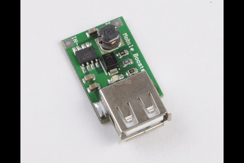
The other device I bought was a cheap-o Chinese converter that came as a two-pack from Hong Kong. It came with a USB connector and took anything 2 to 5V. I tested this with a 2.4V battery pack and it seems to cut out at just under 2V. The efficiency was measured at 77.0%… Also with a 50mA load. My input voltage was a bench power supply set to 3.7V to simulate a LiPo battery on both tests. A nicety of the Chinese “mobile booster” board was the red LED showing output power status. The LED blinks rapidly when it goes into low voltage cutout. The cheap-o board also output 5.20v which was fine for my application. I think I gave roughly $4 both boards with free shipping.


I currently have all projects on hold while I join a BMP085 break out board from SparkFun with a 8pin PIC into a barometer for my upcoming section hike of the PCT in September (I’m fairly certain I wouldn’t have a job nor wife if I declared I was going to through-hike). This year I’m carrying a DeLorme InReach SE stand alone two way satellite communicator so my wife can track me and send the occasional text message. They declare 100 hours of run time but my tests show that 72 hours is average. This isn’t going to cut it…I’ll likely need 1 full recharge to get me through (via USB cable). This led to my decision that the barometer is getting a larger LiPo battery and I am adding a boost converter… In my rush to get anything finished and somewhat tested I sniffed around eBay and found these 2-5V to 5V boost converters (with USB connector) at a ridiculously low price of 2.50$… It’s obviously coming from China. What a great way to spend some eBay bucks?! I can check that one off assuming these aren’t total garbage. I bought two and they claim 87% efficiency at 3.7V. I’ll check them out and post my results. Now I have to decide if I’m going to Bluetooth data to an android device or if I’ll throw an LCD on my project…I think weight will determine my choice.
My homebrew ESR meter spots a cap that is less than desirable. If anyone is interested I have my .asm code I am happy to share. The board is an Olimex prototyping development kit I got from ‘microcontrollershop’. It’s all assembler .. No C version and no desire to work on this anymore. The electrical aspects are documented in the code to some degree (enough that *I* could rebuild it…) I don’t have any plans for a kit. If you want the code you’ll have to agree that you’re building this project for yourself with no re-distribution. I don’t trust my code enough to be considered for some sort of commercial use.

So if anyone runs into an IGBT pack from a York Chiller I’ll do you a solid and give you a pin diagram.
York part number: 031-02061-001
The connector is of this style (p/n from package, I forget which side): 1-794223-0 http://www.digikey.com P/N: A100435CT-ND .. using this you can find both pieces.
.. all TTL is 5V the “/” is a low level input designator. PIN
1: U1 (5VDC)
2: U1+U2 /FAULT
3: U4
4: U5
5: U5+U6 /FAULT
6. T1 (RTD 5K)
7. DC NEG
8. Vcc (5VDC)
9. Isolated Power (I think this is 24VAC but I’m not sure)
10. U2
11. U3
12. U3+U4 /FAULT
13. U6
14. /RESET
15. T2 (RTD)
16. N/C
17. DC NEG
18. Other side of isolated input I believe.. I blew mine up before I could fully test this.
… as for the IGBT it’s 2, 4, 6 are + (up to 1.2kV) and 1, 3, 5 are the negative side, the others are the 3 phase output. New, this pack is painfully expensive.. $1,400 but maybe you’ll run into a good deal or some “garbage” as I did. Good luck!

What a rookie mistake… My variac is grounded… I’ve gotten too spoiled by working on a lot of isolated 24VAC circuits lately… One little check with the scope and boom. PCB death… So much for my one-of-kind short cut. I suppose I need to invest in one of those sets of isolated probes. Silver lining is I didn’t let the smoke out of the front-end of my tektronix scope.
I mocked-up a test of my IGBT Infineon EconoPACK. I had a 24VDC to 95VDC 200w boost brick and fed the IGBT that just because… It made a nice isolated power supply. After I got everything together I feared I had gotten a bad module, but because I know myself I went over everything and realized I failed to pull the /RESET up and so I figure that’s my most likely cause of my inability to get this thing to switch. Everything on the board looks good.. I guess I’ll give it a try again tomorrow. I just got my Pi booted up but I’m hoping I can easily jump in and use it to drive this IGBT pack. If not I’ll just fall back to a PIC. Driving the pack is straight forward; I was just hoping to save myself some development time. This will be my first VFD.. I’m hoping not my last. I scored a 230V 3 phase motor that is about 2 HP. I’m about 95% sure of what I’m going to use this for but I’ll admit it wouldn’t be the first time I stole parts from one project to build another. I’ll see what this Pi can do this weekend after I get back from taking a hike with my daughter on Saturday. I guess Monte Cristo is getting shut down for two years and I want her to experience it. Eight miles is the limit to her hiking abilities right now but she’ll make it, 700ft of elevation gain.. she probably worked harder walking around disney land.
I pulled most of the parts of this project out of storage. While going through old parts I brought back from my house in SD I also found some nifty scintillation detection goodies, gobs of tools, some of my CDP1802 Elf II stuff and a ton of other stuff that I’m sure will make it’s way to my blog. I found a few boxes of 2-20GHz stuff I was ratting away for some EME project but I think I’ll just give that away to a HAM radio club.

 x
x