In 1992 I was in high school going to a magnet school half-time for electronics. During the school year we had a regional electronics competition across the valley with all the school electronics programs in area. I don’t remember every bit of the competition; but as you can imagine there was theory, circuit analysis, math, troubleshooting and a practical soldering test. I somehow pulled off first place.. but not without having to pull off a soldering feat! Someone must have donated old through-hole aerospace related PCBs. There was a huge box of PCBs and they all had one ugly thing in common: Every single one had a thick layer of conformal coating! I’m guessing they came from Boeing. I was lucky; I’d run into these before or I’d likely not have won the competition. But I’ll get to that… Conformal coating comes in five (some claim six) types: Silicone, Epoxy, Acrylic, Polyurethane, and I’ll roll it up in “others”. They each have their application depending on your needs.. dielectric strength, flexibility, moisture resistance, etc. I typically use Silicone because it is flexible, and has good moisture resistance. The rest of this conversation is probably best viewed in video; so with that…
warning: this video drags on a little, 9 minutes could have easily been 4. I’m still not great at the whole video thing and I decided just to do this in one take.
Back to high-school days competition; the challenge was simple. Remove a two components and replace with new parts. I had gotten lucky that they had used acrylic coating and I chipped/scraped away most of the conformal coating without much damage or scaring. Everyone else just went and burnt through the coating to de-solder their targets… well as you can imagine it turned into a mess. Mine wasn’t anything I’d nail on a wall but apparently it was enough to be “award winning” 🙂
I purchased a Silicon Labs Si4707 weather band radio break out board (BOB) from Sparkfun a couple of months ago and finally did something with it. The Si4707 has a SAME ( Specific Area Message Encoding ) processor that allows alerting for only for a certain kinds of warnings. The weather band radio board receives from 162.40MHz to 162.55MHz; Its outputs is a 1/8″ jack with enough output to power a small speaker with low volume or earphones at a comfortable level of listening.
LCD Display of Si4707 Weather Band Radio Project
For my project I used MPLABX 2.0 with the XC8 C compiler. I decide to post this project before I was done programming because I’m about to customize this project for what I want. I thought it was a good time to make it available if a reader was interested in customizing the project without all the work of tearing apart what I had done. The code has all the right nuts and bolts and at most of the hard work done for you. All a person needs to do is a little(?) configuration to make the project meet your needs. You might consider going in another direction; volume up/down (programmable feauture!), tune up/down, and of course working with the SAME information, who knows?
Right now on the bench the PIC powers up, resets and powers up the radio, then tunes the radio via I2C to 162.55MHz. It finishes up by reading back the status and then dumps the Tuned Frequency and RSSI ( Received Signal Strength Indicator ) on to the LCD… then off to infinite loop land. In the next few days I plan on having my seven buttons for “quick tune” to the common frequencies (.40, 425, .45, etc..) and one additional monitor/standby switch. My radio will normally be silent and once it receives a weather alert it will un-mute the speaker and alert the LCD. The Standby/Monitor button will reset my alert.
I’ll throw my finished code up on github and you can download my version in a week or so [I’ll edit this and drop a link in when I’ve actually done this].
Another note of interest: the output of the audio amplifier is kind of weak. I recommend building another amplifier stage if you want the thing to wake you up in a weather emergency.
The attached code this is really rough around the edges.. I lot of hacking went into this and all of the unused functions are totally untested.
The Si4707 WX RX:
Okay, so $30.. not a bad price. And in the end I’m happy with the performance.
HOWEVER! The items I don’t like about it…
1. Sparkfun’s BOB threw pull up resistors on it.. that is annoying. I realize you can cut them out but .. how about some 2mm jumpers or something? I got burnt by them trying to get the I2C working. (RTFM!) 🙂 I noticed lot of people seem to have issues with them being poorly sized according to the feedback I’ve read.
2. Wow it this thing pokey. I was a little confused by the application note for the product to determine worst case tune time, etc… basically I just ended up putting in 1000ms because 300ms was hit and miss for me. If I read it correctly worse case tune time for the AM radio version of the chip is 28 seconds!?
3. I2C! Well it worked fine but I suspect the board is a little noisy? with about 2 inches of wire leads I got enough ringing when the BOB wasn’t loaded by the logic analyzer for comm to fold. I ended up have to enable slew. I also slowed the unit down to 25KHz from 100KHz because I have to wait for it anyways. It’ll probably work fine at 100KHz with slew on.
Top view of Si4707 Weather Band Radio Project. The power supply sits on the back of the LCD/keypad support board and the weather band sits sandwiched between the TAUTIC dev board and daughter-protoboard. The speaker was just thrown in there for quick testing.
The circuit in general:
I haven’t included a schematic nor do I have any plans to. The photos show you I really am not using any support components besides LCD 10k pot you normally put on an LCD. I would have had pull up resistors but they were not required because of the BOB having them pre-installed. You should be able to re-create the circuit just by looking at my TRISx/LATx initialization in the code. I commented it my version of adequate-enough… If you’re stumped, just ask!
5.0V input to run the LCD backlight and LCD main power (a standard 2 line 44780 compatible). The five volts also feeds the switching power supply to supply the PIC and 4707 with 3.3V power. I mistakenly thought the 4707 ran on 3.3V because I had been using an I2C product that was 3.3V only then had done a little switching around, oops… no harm, just a waste of the regulator. The 4707 runs 2.7-5.5V. My push button switches are designed to run in a 2×4 matrix. See the //notes in the code. Finally my PIC. I’m using (again!) the Microchip PIC 16F1509 microcontroller with a Tautic 20 pin development board and it’s daughter-board for a little prototyping space. I could maybe stretch this 20 PIN MCU a little more but I probably should have picked a slightly larger PIC for the IO. It’s enough for me though.
Side view. Note the whole project was just slapped on top of a piece of old PCB.. It’s not even FR4.. just some old stuff. I made some “mounts” out of small copper strap and soldered the protoboard to the bare copper clad board.
So my final thoughts are I still have a lot of work and a lot of clean up work on this project. My temp mounting doesn’t have me totally won over. I also don’t like my “keypad” … I might by a pre-build “shield” and adapt it or maybe design my own PCB. I haven’t even hooked up the buttons because I haven’t decided if I’m happy-enough if the hardware.
The code:
/*
 * File:   newmain.c
 * Author: Charles M Douvier
 * Contact at: http://iradan.com
 *
 * Created on January 26, 2014, 12:00 PM
 *
 * Target Device:
 * 16F1509 on Tautic 20 pin dev board
 *
 * Project:
 *  I2C Testing with the TCN75A
 *
 * Version:
 * 0.1  Start Bit, and Control Byte ... check
 * 0.2  /ACK NAK and Stop ... check!
 * 0.3  works+232
 *
 */
#ifndef _XTAL_FREQ
#define _XTAL_FREQ 4000000 //4Mhz FRC internal osc
#define __delay_us(x) _delay((unsigned long)((x)*(_XTAL_FREQ/4000000.0)))
#define __delay_ms(x) _delay((unsigned long)((x)*(_XTAL_FREQ/4000.0)))
#endif

#include
#include
#include
#include

//config bits
#pragma config FOSC=INTOSC, WDTE=OFF, PWRTE=ON, MCLRE=ON, CP=OFF, BOREN=OFF, CLKOUTEN=OFF, FCMEN=OFF
#pragma config WRT=OFF, STVREN=OFF, LVP=OFF


#define _XTAL_FREQ 4000000 //defined for delay
#define device_address  0b1001000       // unused for now

    unsigned int ACK_bit;
    int i, x;   //garbage flags
    long int tempi, tempn, tempx, tempy, temp10, temp25;
    unsigned char byte, tempbyte1, tempbyte2;
    unsigned char StatusByte;
    unsigned char RESP1Byte, RESP2Byte, RESP3Byte, RESP4Byte, RESP5Byte;
    unsigned char RESP6Byte, RESP7Byte, RESP8Byte, RESP9Byte, RESP10Byte;
    unsigned char RESP11Byte, RESP12Byte, RESP13Byte, RESP14Byte;
    char buf[10];

void init_io(void) {

    ANSELA = 0x00; // all port A pins are digital I/O
    ANSELB = 0x00; // all port A pins are digital I/O
    ANSELC = 0x00; // all port B pins are digital I/O

    TRISAbits.TRISA0 = 0; // keypad strobe 1
    TRISAbits.TRISA1 = 0; // keypad strobe 2
    TRISAbits.TRISA2 = 0; // RADIO /RST
    TRISAbits.TRISA3 = 1; // /MCLR
    TRISAbits.TRISA4 = 0; // LCD RS
    TRISAbits.TRISA5 = 0; // LCD EN

    TRISBbits.TRISB4 = 1; // RB4 I2C SDA, has to be set as an input
    TRISBbits.TRISB5 = 1; // RB5 NC (RESERVED RS232)
    TRISBbits.TRISB6 = 1; // RB6 I2C SCLK, has to be set as an input
    TRISBbits.TRISB7 = 0; // RB7 NC (RESERVED RS232)

    TRISCbits.TRISC0 = 0; // LCD D4
    TRISCbits.TRISC1 = 0; // LCD D5
    TRISCbits.TRISC2 = 0; // LCD D6
    TRISCbits.TRISC3 = 0; // LCD D7
    TRISCbits.TRISC4 = 1; // button col 1
    TRISCbits.TRISC5 = 1; // button col 2
    TRISCbits.TRISC6 = 1; // button col 3
    TRISCbits.TRISC7 = 1; // button col 4
}

/*
 *  LCD Interface Functions
 *  standard 44780 format 2 lines
 */

void lcd_strobe (void)  //TOGGLE LCD_EN
{
    LATAbits.LATA5 = 0;
    __delay_ms(20);
    LATAbits.LATA5 = 1;
}

/* write a byte to the LCD in 4 bit mode */

void lcd_write(unsigned char c)
{
	LATC = c >> 4;
	lcd_strobe();
	LATC = c;
	lcd_strobe();
        __delay_us(100);
}

/*
 * 	Clear and home the LCD
 */

void lcd_clear(void)
{
	LATAbits.LATA4 = 0;
	lcd_write(0x1);
        __delay_ms(2);
}


/* write a string of chars to the LCD */

void lcd_puts(const char * s)
{
	LATAbits.LATA4 = 1;	// write characters
	while(*s)
		lcd_write(*s++);
}

/*
 * Go to the specified position
 */

void lcd_goto(unsigned char pos)
{
	LATAbits.LATA4 = 0;
	lcd_write(0x80+pos);
}

/*
 *      Write 16 spaces on LCD 2 to avoid blanking, (ugly CLEAR effect)
 *      this is slow but work for my needs
 */

void    lcd_clrline1(void)
{
    lcd_goto(0);
    lcd_puts("                ");
    lcd_goto(0);
}

void    lcd_clrline2(void)
{
    lcd_goto(40);
    lcd_puts("                ");
    lcd_goto(40);
}

/* initialise the LCD - put into 4 bit mode */

void lcd_init(void)
{
	LATAbits.LATA4 = 0;	// write control bytes
        LATC = 0x03;
        __delay_ms(150);         //power on delay
	lcd_strobe();
        __delay_ms(5);
	lcd_strobe();
        __delay_ms(5);
	lcd_strobe();
        __delay_ms(5);
	LATC = 0x02;             // set 4 bit mode
        __delay_ms(5);
	lcd_strobe();
        __delay_ms(5);
	lcd_write(0x28);	// 4 bit mode, 1/16 duty, 5x8 font
	lcd_write(0x08);	// display off
	lcd_write(0x0C);	// display on cursor+blink off
	lcd_write(0x06);	// entry mode
}

/*
 *  I2C Functions
 *
 */

void I2C_ACK(void)
{
   PIR1bits.SSP1IF=0;          // clear SSP interrupt bit
   SSP1CON2bits.ACKDT=0;        // clear the Acknowledge Data Bit - this means we are sending an Acknowledge or 'ACK'
   SSP1CON2bits.ACKEN=1;        // set the ACK enable bit to initiate transmission of the ACK bit to the serial eeprom
   while(!PIR1bits.SSP1IF);    // Wait for interrupt flag to go high indicating transmission is complete
}

void Send_I2C_Data(unsigned int databyte)
{
    PIR1bits.SSP1IF=0;          // clear SSP interrupt bit
    SSPBUF = databyte;              // send databyte
    while(!PIR1bits.SSP1IF);    // Wait for interrupt flag to go high indicating transmission is complete
}

unsigned char RX_I2C_Data (void)
{

    RCEN = 1;               //
    while( RCEN ) continue;
    while( !BF ) continue;
    byte = SSPBUF;
   return byte;
}

void I2C_Control_Write(void)
{
    PIR1bits.SSP1IF=0;          // clear SSP interrupt bit
    SSP1BUF = 0xC6;             // send the control byte 4707 Addr w/ SEN=1
    while(!PIR1bits.SSP1IF)     // Wait for interrupt flag to go high indicating transmission is complete
        {
        i = 1;
          // place to add a breakpoint if needed
        }
    PIR1bits.SSP1IF=0;

}

void I2C_Control_Read(void)
{
    PIR1bits.SSP1IF=0;          // clear SSP interrupt bit
    SSP1BUF = 0xC7;             // send the control byte
    while(!PIR1bits.SSP1IF)     // Wait for interrupt flag to go high indicating transmission is complete
        {
        i = 1;
          // place to add a breakpoint if needed
        }
    PIR1bits.SSP1IF=0;
   }

void I2C_Start_Bit(void)
{
    PIR1bits.SSP1IF=0;          // clear SSP interrupt bit
    SSPCON2bits.SEN=1;          // send start bit
    while(!PIR1bits.SSP1IF)    // Wait for the SSPIF bit to go back high before we load the data buffer
        {
        i = 1;
        }
    PIR1bits.SSP1IF=0;
}

void I2C_check_idle()
{
    unsigned char byte1; // R/W status: Is a transfer in progress?
    unsigned char byte2; // Lower 5 bits: Acknowledge Sequence, Receive, STOP, Repeated START, START

    do
    {
        byte1 = SSPSTAT & 0x04;
        byte2 = SSPCON2 & 0x1F;
    } while( byte1 | byte2 );
}
/*
 * Send the repeated start message and wait repeated start to finish.
 */
void I2C_restart()
{
    I2C_check_idle();
    RSEN = 1; // Reinitiate start
    while( RSEN ) continue;
}

void I2C_Stop_Bit(void)
{
    PIR1bits.SSP1IF=0;          // clear SSP interrupt bit
    SSPCON2bits.PEN=1;          // send stop bit
    while(!PIR1bits.SSP1IF)
    {
        i = 1;
        // Wait for interrupt flag to go high indicating transmission is complete
    }
}

void I2C_NAK(void)
{
    PIR1bits.SSP1IF=0;           // clear SSP interrupt bit
    SSP1CON2bits.ACKDT=1;        // set the Acknowledge Data Bit- this means we are sending a No-Ack or 'NAK'
    SSP1CON2bits.ACKEN=1;        // set the ACK enable bit to initiate transmission of the ACK bit to the serial eeprom
    while(!PIR1bits.SSP1IF)     // Wait for interrupt flag to go high indicating transmission is complete
    {
        i = 1;
    }
}

/*
 *  Si4707 WB RX Functions
 *
 */

void Tune400(void)
{
//162400	64960	FDC0

    I2C_Start_Bit();                     // send start bit
    I2C_Control_Write();                 // send control byte

    Send_I2C_Data(0x50);                 //Tune Frequency
    Send_I2C_Data(0x00);                 //0x00
    Send_I2C_Data(0xFD);                 //
    Send_I2C_Data(0xC0);                 //...

    I2C_Stop_Bit();

    __delay_ms(1000);					//tune delay
}

void Tune425(void)
{
//162425	64970	FDCA

    I2C_Start_Bit();                     // send start bit
    I2C_Control_Write();                 // send control byte

    Send_I2C_Data(0x50);                 //Tune Frequency
    Send_I2C_Data(0x00);                 //0x00
    Send_I2C_Data(0xFD);                 //
    Send_I2C_Data(0xCA);                 //...

    I2C_Stop_Bit();

    __delay_ms(1000);					//tune delay
}

void Tune450(void)
{
//162450	64980	FDD4

    I2C_Start_Bit();                     // send start bit
    I2C_Control_Write();                 // send control byte

    Send_I2C_Data(0x50);                 //Tune Frequency
    Send_I2C_Data(0x00);                 //0x00
    Send_I2C_Data(0xFD);                 //
    Send_I2C_Data(0xD4);                 //...

    I2C_Stop_Bit();

    __delay_ms(1000);					//tune delay
}

void Tune475(void)
{
//162475	64990	FDDE

    I2C_Start_Bit();                     // send start bit
    I2C_Control_Write();                 // send control byte

    Send_I2C_Data(0x50);                 //Tune Frequency
    Send_I2C_Data(0x00);                 //0x00
    Send_I2C_Data(0xFD);                 //
    Send_I2C_Data(0xDE);                 //...

    I2C_Stop_Bit();

    __delay_ms(1000);					//tune delay
}

void Tune500(void)
{
//162500	65000	FDE8

    I2C_Start_Bit();                     // send start bit
    I2C_Control_Write();                 // send control byte

    Send_I2C_Data(0x50);                 //Tune Frequency
    Send_I2C_Data(0x00);                 //0x00
    Send_I2C_Data(0xFD);                 //
    Send_I2C_Data(0xE8);                 //...

    I2C_Stop_Bit();

    __delay_ms(1000);					//tune delay
}

void Tune525(void)
{
//162525	65010	FDF2

    I2C_Start_Bit();                     // send start bit
    I2C_Control_Write();                 // send control byte

    Send_I2C_Data(0x50);                 //Tune Frequency
    Send_I2C_Data(0x00);                 //0x00
    Send_I2C_Data(0xFD);                 //
    Send_I2C_Data(0xF2);                 //...

    I2C_Stop_Bit();

    __delay_ms(1000);					//tune delay
}

void Tune550(void)
{
//162550	65020	FDFC

    I2C_Start_Bit();                     // send start bit
    I2C_Control_Write();                 // send control byte

    Send_I2C_Data(0x50);                 //Tune Frequency
    Send_I2C_Data(0x00);                 //0x00
    Send_I2C_Data(0xFD);                 //
    Send_I2C_Data(0xFC);                 //...

    I2C_Stop_Bit();

    __delay_ms(1000);					//tune delay
}

void VolumeUp(void)
{
//future use
}

void VolumeDown(void)
{
//future use
}

void VolumeMAX (void)
{
    // Reset Volume
}
void VolumeMUTE (void)
{
    //Mute Sound

}

void CheckStatus (void)
{
/*
 * STATUS BYTE
 *	[7] CTS	Clear to Send.
 *	0 = Wait before sending next command.
 *	1 = Clear to send next command.

 *	[6] ERR	Error.
 *	0 = No error
 *	1 = Error

 *	5:4 Reserved Values may vary.

 *	[3] RSQINT	Received Signal Quality Interrupt.
 *	0 = Received Signal Quality measurement has not been triggered.
 *	1 = Received Signal Quality measurement has been triggered.

 *	[2] SAMEINT	SAME Interrupt (Si4707 Only).
 *	0 = SAME interrupt has not been triggered.
 *	1 = SAME interrupt has been triggered.

 *	[1] ASQINT	Audio Signal Quality Interrupt.
 *	0 = Audio Signal Quality measurement has not been triggered.
 *	1 = Audio Signal Quality measurement has been triggered.

 *	[0] STCINT	Seek/Tune Complete Interrupt.
 *	0 = Tune complete has not been triggered.
 *	1 = Tune complete interrupt has been triggered.

*/
//0x52 RX_STATUS
//STATUS, RESP1 (VALID), RESP2 FREQ_H, RESP3 FREQ_L, RESP4 RSSI, RESP5 SNR

    I2C_Start_Bit();                     // send start bit
    I2C_Control_Write();
    Send_I2C_Data(0x52);                //TUNE STATUS
    Send_I2C_Data(0x00);                //DONT CLEAR INT

    I2C_restart();
    I2C_Control_Read();

    RX_I2C_Data();                      //STATUS
	StatusByte = byte;
    I2C_ACK();

	RX_I2C_Data();                      //VALID
	RESP1Byte = byte;
    I2C_ACK();

	RX_I2C_Data();                      //FREQ1
	RESP2Byte = byte;
    I2C_ACK();

	RX_I2C_Data();                      //FREQ2
	RESP3Byte = byte;
    I2C_ACK();

	RX_I2C_Data();                      //RSSI
	RESP4Byte = byte;
    I2C_ACK();

    RX_I2C_Data();                      //SNR
	RESP5Byte = byte;
    I2C_NAK();                          //NAK

	I2C_Stop_Bit();                     // Send Stop Bit

//Update Freq Display
//Update RSSI
}


CheckFlag(unsigned value, unsigned bitindex)
{
//1=0x000000_0
//CheckFlag(BYTE,1);

    return (value & (1 << bitindex)) != 0;
}


void CheckSAME(void)
{
//0x54   SAME_STATUS
//STATUS, ARG1, ARG2, STATUS, RESP1-RESP13.
//
//ARG1 0:INTACK 1:CLRBUF
//ARG2 READ_ADDR
//3:RSQINT 2:SAMEINT 1:ASQINT 0:STCINT

    I2C_Start_Bit();                     // send start bit
    I2C_Control_Write();
    Send_I2C_Data(0x54);                //SAME STATUS
    Send_I2C_Data(0x00);                //DONT CLEAR INT
	Send_I2C_Data(0x00);                //Start location

    I2C_restart();
    I2C_Control_Read();

    RX_I2C_Data();                      //STATUS
	StatusByte = byte;
    I2C_ACK();

	RX_I2C_Data();                      //
	RESP1Byte = byte;
    I2C_ACK();

	RX_I2C_Data();                      //
	RESP2Byte = byte;
    I2C_ACK();

	RX_I2C_Data();                      //
	RESP3Byte = byte;
    I2C_ACK();

	RX_I2C_Data();                      //
	RESP4Byte = byte;
    I2C_ACK();

	RX_I2C_Data();                      //
	RESP5Byte = byte;
    I2C_ACK();

	RX_I2C_Data();                      //
	RESP6Byte = byte;
    I2C_ACK();

	RX_I2C_Data();                      //
	RESP7Byte = byte;
    I2C_ACK();

	RX_I2C_Data();                      //
	RESP8Byte = byte;
    I2C_ACK();

	RX_I2C_Data();                      //
	RESP9Byte = byte;
    I2C_ACK();

	RX_I2C_Data();                      //
	RESP10Byte = byte;
    I2C_ACK();

	RX_I2C_Data();                      //
	RESP11Byte = byte;
    I2C_ACK();

	RX_I2C_Data();                      //
	RESP12Byte = byte;
    I2C_ACK();

    RX_I2C_Data();                      //
	RESP13Byte = byte;
    I2C_NAK();                          //NAK

	I2C_Stop_Bit();                     // Send Stop Bit

        if (CheckFlag(StatusByte,2))
            i=1;    //TODO
}


void ResetSAME(void)
{
//0x54   SAME_STATUS
//STATUS, ARG1, ARG2, STATUS, RESP1-RESP13.
//ARG1 0:INTACK 1:CLRBUF
//ARG2 READ_ADDR
//3:RSQINT 2:SAMEINT 1:ASQINT 0:STCINT

    I2C_Start_Bit();                     // send start bit
    I2C_Control_Write();
    Send_I2C_Data(0x54);                //SAME STATUS
    Send_I2C_Data(0x03);                //Dump Buffer and Reset SAME Int.
	Send_I2C_Data(0x00);                //Start location

    I2C_restart();
    I2C_Control_Read();

    RX_I2C_Data();                      //STATUS
	StatusByte = byte;
    I2C_ACK();

	RX_I2C_Data();                      //don't care about the rest..
    I2C_ACK();

	RX_I2C_Data();                      //
    I2C_ACK();

	RX_I2C_Data();                      //
    I2C_ACK();

	RX_I2C_Data();                      //
    I2C_ACK();

	RX_I2C_Data();                      //
    I2C_ACK();

	RX_I2C_Data();                      //
    I2C_ACK();

	RX_I2C_Data();                      //
    I2C_ACK();

	RX_I2C_Data();                      //
    I2C_ACK();

	RX_I2C_Data();                      //
    I2C_ACK();

	RX_I2C_Data();                      //
    I2C_ACK();

	RX_I2C_Data();                      //
    I2C_ACK();

	RX_I2C_Data();                      //
    I2C_ACK();

    RX_I2C_Data();                      //
    I2C_NAK();                          //NAK

	I2C_Stop_Bit();                     // Send Stop Bit
}


void Monitor(void)
{
    //TODO

}

void Standby(void)
{
    //TODO

}

MultiFunction()
{
LATAbits.LATA0=0;   //TODO
LATAbits.LATA1=1;

__delay_ms(2000);

	if (LATCbits.LATC3)
	Monitor();
	else
	Standby();

}

poll_buttons()      //TODO
{
//check buttons for switch. no need for debounce, polling is long in the case of keydown.

LATAbits.LATA0=1;
LATAbits.LATA1=0;
__delay_ms(5);

if (LATCbits.LATC4)
	Tune400();
if (LATCbits.LATC5)
	Tune425();
if (LATCbits.LATC6)
	Tune450();
if (LATCbits.LATC7)
	Tune475();

LATAbits.LATA0=0;
LATAbits.LATA1=1;
__delay_ms(5);

if (LATCbits.LATC4)
	Tune500();
if (LATCbits.LATC1)
	Tune525();
if (LATCbits.LATC2)
	Tune550();
if (LATCbits.LATC3)
	MultiFunction();
}

void RST_4707(void)
{
        LATAbits.LATA2 = 0;
        __delay_ms(50);
        LATAbits.LATA2 = 1;
}

void display_missing(void)
{
    lcd_clrline1();

    lcd_puts("Si4707 missing.");
}

void display_freq(void)
{
    lcd_clrline1();

    lcd_puts("FREQ: ");
    CheckStatus();
    //RESP4Byte
    temp25 = 25;
    temp10 = 10;
    tempn = RESP2Byte;
    tempy = 256;
    tempx = RESP3Byte;
    tempi = tempn*tempy;
    tempi = tempi+tempx;
    tempi = tempi*temp25;
    tempi = tempi/temp10;

    ltoa(buf,tempi,10);  //long conversion to buffer
    lcd_puts(buf);
    lcd_puts(" KHz");
}

int main(void) {

    OSCCONbits.IRCF = 0x0d;     //set OSCCON IRCF bits to select OSC frequency 4MHz
    OSCCONbits.SCS = 0x02;
    OPTION_REGbits.nWPUEN = 0;  //enable weak pullups (each pin must be enabled individually)

    init_io();

    __delay_ms(250);            //let the power settle

     lcd_init();
    __delay_ms(10);
     lcd_clear();

                                //display test message
    lcd_puts("iradan.com/");
    lcd_goto(40);

    TRISBbits.TRISB6 = 1;

    SSPSTATbits.SMP = 1;
    SSPCONbits.SSPM=0x08;       // I2C Master mode, clock = Fosc/(4 * (SSPADD+1))
    SSPCONbits.SSPEN=1;         // enable MSSP port
    SSPADD = 0x27;              //figure out which one you can ditch sometime (probably either)
    SSP1ADD = 0x27;             // 100KHz
                                //0x09 = 100KHz
    // **************************************************************************************

    RST_4707();

    __delay_ms(100);                    // let everything settle.

    I2C_Start_Bit();                    // send start bit
    I2C_Control_Write();                // send control byte with read set

    x=0;                                // temp feature, TODO
    if (!SSP1CON2bits.ACKSTAT)
    x=1;                 //device there? /ACked?

    Send_I2C_Data(0x01);                //power up
    Send_I2C_Data(0x53);                //command per AN332
    Send_I2C_Data(0x05);
    I2C_Stop_Bit();

    __delay_ms(1000);                     //power up delay...

    I2C_Start_Bit();                     // send start bit
    I2C_Control_Write();                 // send control byte
    Send_I2C_Data(0x50);                 //Tune Frequency
    Send_I2C_Data(0x00);                 //0x00
    Send_I2C_Data(0xFD);                 //65020 (162.550)
    Send_I2C_Data(0xFC);                 //... FDFC
    I2C_Stop_Bit();

    __delay_ms(1000);                    //tuning delay

    if (x==1)
        display_freq();
    else
        display_missing();

    lcd_clrline2();   //clear LCD line 2 by writting " " and return
    lcd_puts("RSSI: ");
    tempi = RESP4Byte;
    ltoa(buf,tempi,10);  //long conversion to buffer
    lcd_puts(buf);

    while (1) {
        poll_buttons();
        i=1;    //  do nothing for now..
        __delay_ms(100);                      // delay.. just because
    }
    return;
}
I know I’ve been doing a lot of these code tidbits lately but it’s what has been driving me to sit at the bench. This is my first I2C project.. I pulled heavily from many sources of snippets, documentation and projects; microchip forums (*some of it wrong*), app data, both pieces of product data and a lot of trial and error… mostly error.
In a run up to my weather radio project I needed to get familiar with using I2C with the XC8 compiler. I’ve been focusing most of my experimenting with the 16F1509 lately so I’ll be sticking with it again here. I switched to the ‘1509 from the 16F628A. In the future I have the 16F916 I have plans for and then I’ll go back to the 18F series to work on the USB project in the no-so-distant future.
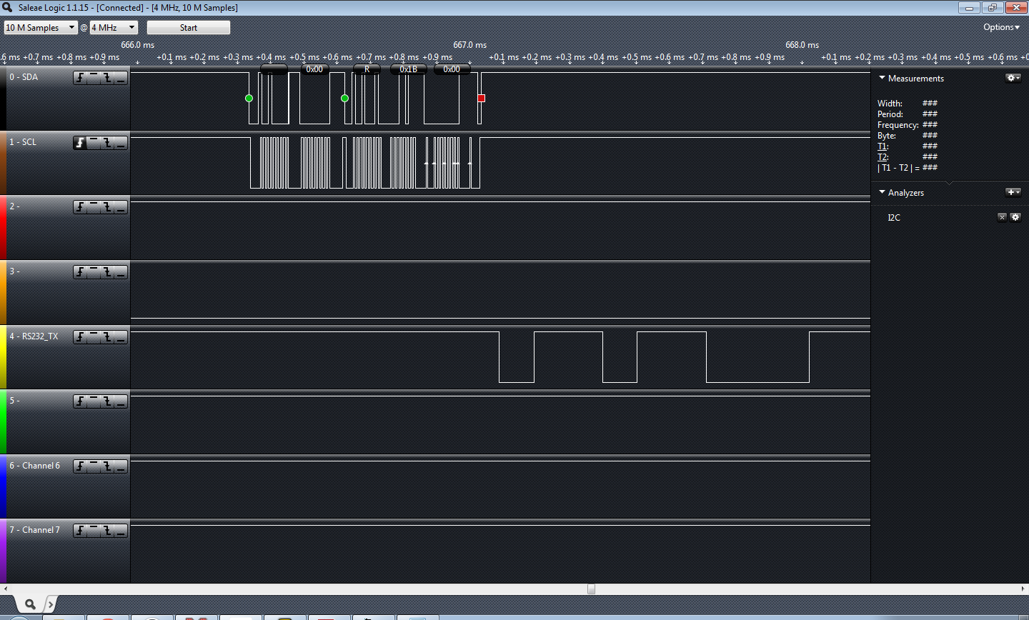
Before I prepared to working on this project Jayson Tautic mentioned you don’t work on I2C without a logic analyzer; I’ve never known a person to be so absolutely correct about anything, ever. So, I bought one. My little logic analyzer was absolutely required, I know I wouldn’t have gotten this finished without it. You’ll note the screen shot… catching these little burps with a scope would have been pretty difficult.
Successful read of the TCN75A
I’m really thankful he recommended the Saleae. It was on the top of my list but his recommendation sold me on pulling the trigger.
This article is not to explain or go into the I2C protocol, there are a ton of “101” articles out there.. just pick one, or two, or three. I started with this one from embedded lab.
I picked the TCN75A temp sensor for this I2C test. I had a BMP085 but I accidentally blew it up on 5V when I threw my RS-232 board on and forgot I had the sensor still plugged in… Ooops! The BMP085 is a 3.3V device. I really need to buy a dual breadboard power supply one of these days!
In short to communicate with this TCN75A you write the “Write” control byte to the I2C bus, you look for your /ACK set your pointer and set the configuration byte… wait “forever” (240ms according to DS21935A) for the conversion, write the write control byte address, set the pointer, restart, write the “read” control byte and grab your two bytes of temperature data. You should /ACK the first byte of received data.. NAK the second. I made the mistake of /ACKing both bytes.. that causes the I2C slave to hang the SDA low..
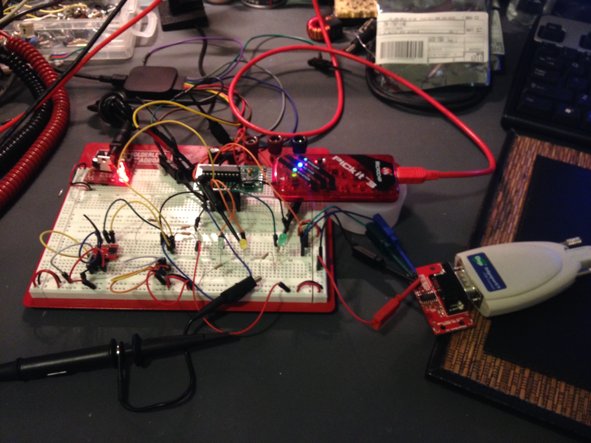
The circuit… TCN75 on the bottom left of the breadboard. The PIC microcontroller is the think the PICKit3 is plugged into and I’m dumping the raw data to RS-232 (bottom right).
So it worked… I dumped the raw info to the UART. I didn’t really feel like dumping it to an LCD or anything since I’d be more likely to use this for telemetry than for a local display. It’s a good starting block to a vasic project. I’ll add the code on my code sample page later on this weekend but for now you can find it below….
The code:
/*
 * File: newmain.c
 * Author: Charles M Douvier
 * Contact at: http://iradan.com
 *
 * Created on January 26, 2014, 12:00 PM
 *
 * Target Device:
 * 16F1509 on Tautic 20 pin dev board
 *
 * Project:
 * I2C Testing with the TCN75A
 *
 * Version:
 * 0.1 Start Bit, and Control Byte ... check
 * 0.2 /ACK NAK and Stop ... check!
 * 0.3 works+232
 *
 */
#ifndef _XTAL_FREQ
#define _XTAL_FREQ 4000000 //4Mhz FRC internal osc
#define __delay_us(x) _delay((unsigned long)((x)*(_XTAL_FREQ/4000000.0)))
#define __delay_ms(x) _delay((unsigned long)((x)*(_XTAL_FREQ/4000.0)))
#endif
TRISBbits.TRISB4 = 1; // RB4 I2C SDA, has to be set as an input
 TRISBbits.TRISB5 = 1; // RB5 = nc
 TRISBbits.TRISB6 = 1; // RB6 I2C SCLK, has to be set as an input
 TRISBbits.TRISB7 = 0; // RS232 TX
while(!TXSTAbits.TRMT); // make sure buffer full bit is high before transmitting
 TXREG = mydata_byte; // transmit data
}
void serial_init(void)
{
// calculate values of SPBRGL and SPBRGH based on the desired baud rate
 //
 // For 8 bit Async mode with BRGH=0: Desired Baud rate = Fosc/64([SPBRGH:SPBRGL]+1)
 // For 8 bit Async mode with BRGH=1: Desired Baud rate = Fosc/16([SPBRGH:SPBRGL]+1)
 RCSTAbits.SPEN=1; // serial port is enabled
 RCSTAbits.RX9=0; // select 8 data bits
 RCSTAbits.CREN=1; // receive enabled
SPBRGL=25; // here is calculated value of SPBRGH and SPBRGL
 SPBRGH=0;
PIR1bits.RCIF=0; // make sure receive interrupt flag is clear
 PIE1bits.RCIE=1; // enable UART Receive interrupt
 INTCONbits.PEIE = 1; // Enable peripheral interrupt
 INTCONbits.GIE = 1; // enable global interrupt
__delay_ms(50); // give time for voltage levels on board to settle
 uart_xmit('R'); // transmit some data
 uart_xmit('S');
 uart_xmit('T');
}
void I2C_ACK(void)
{
 PIR1bits.SSP1IF=0; // clear SSP interrupt bit
 SSP1CON2bits.ACKDT=0; // clear the Acknowledge Data Bit - this means we are sending an Acknowledge or 'ACK'
 SSP1CON2bits.ACKEN=1; // set the ACK enable bit to initiate transmission of the ACK bit to the serial eeprom
 while(!PIR1bits.SSP1IF); // Wait for interrupt flag to go high indicating transmission is complete
}
void Send_I2C_Data(unsigned int databyte)
{
 PIR1bits.SSP1IF=0; // clear SSP interrupt bit
 SSPBUF = databyte; // send databyte
 while(!PIR1bits.SSP1IF); // Wait for interrupt flag to go high indicating transmission is complete
}
void I2C_Control_Write(void)
{
 PIR1bits.SSP1IF=0; // clear SSP interrupt bit
 SSP1BUF = 0x90; // send the control byte (90 TCN75, EF BMP085)
 while(!PIR1bits.SSP1IF) // Wait for interrupt flag to go high indicating transmission is complete
 {
 i = 1;
 // place to add a breakpoint if needed
 }
 PIR1bits.SSP1IF=0;
}
void I2C_Control_Read(void)
{
 PIR1bits.SSP1IF=0; // clear SSP interrupt bit
 SSP1BUF = 0x91; // send the control byte (90 TCN75, EF BMP085)
 while(!PIR1bits.SSP1IF) // Wait for interrupt flag to go high indicating transmission is complete
 {
 i = 1;
 // place to add a breakpoint if needed
 }
 PIR1bits.SSP1IF=0;
 }
void I2C_Start_Bit(void)
{
 PIR1bits.SSP1IF=0; // clear SSP interrupt bit
 SSPCON2bits.SEN=1; // send start bit
 while(!PIR1bits.SSP1IF) // Wait for the SSPIF bit to go back high before we load the data buffer
 {
 i = 1;
 }
 PIR1bits.SSP1IF=0;
}
void I2C_check_idle()
{
 unsigned char byte1; // R/W status: Is a transfer in progress?
 unsigned char byte2; // Lower 5 bits: Acknowledge Sequence, Receive, STOP, Repeated START, START
void I2C_Stop_Bit(void)
{
 PIR1bits.SSP1IF=0; // clear SSP interrupt bit
 SSPCON2bits.PEN=1; // send stop bit
 while(!PIR1bits.SSP1IF)
 {
 i = 1;
 // Wait for interrupt flag to go high indicating transmission is complete
 }
}
void I2C_NAK(void)
{
 PIR1bits.SSP1IF=0; // clear SSP interrupt bit
 SSP1CON2bits.ACKDT=1; // set the Acknowledge Data Bit- this means we are sending a No-Ack or 'NAK'
 SSP1CON2bits.ACKEN=1; // set the ACK enable bit to initiate transmission of the ACK bit to the serial eeprom
 while(!PIR1bits.SSP1IF) // Wait for interrupt flag to go high indicating transmission is complete
 {
 i = 1;
 }
}
int main(void) {
OSCCONbits.IRCF = 0x0d; //set OSCCON IRCF bits to select OSC frequency 4MHz
 OSCCONbits.SCS = 0x02;
 OPTION_REGbits.nWPUEN = 0; //enable weak pullups (each pin must be enabled individually)
init_io();
 serial_init();
SSPCONbits.SSPM=0x08; // I2C Master mode, clock = Fosc/(4 * (SSPADD+1))
 SSPCONbits.SSPEN=1; // enable MSSP port
 SSPADD = 0x09; //figure out which one you can ditch sometime (probably either)
 SSP1ADD = 0x09; // 100KHz
 // **************************************************************************************
__delay_ms(50); // let everything settle.
 I2C_Start_Bit(); // send start bit
 I2C_Control_Write(); // send control byte with read set
if (!SSP1CON2bits.ACKSTAT)
 LATCbits.LATC1 = 0; //device /ACked?
Send_I2C_Data(0x01); //pointer
 Send_I2C_Data(0xE1); //1 shot, 12bit res
 I2C_Stop_Bit();

 __delay_ms(500); //wait for conversion
I2C_Start_Bit(); // send start bit
 I2C_Control_Write(); // send control byte with read set
 if (!SSP1CON2bits.ACKSTAT)
 LATCbits.LATC1 = 0;
 Send_I2C_Data(0x00); //pointer
I didn’t read a forum post all the way through (or maybe I was just tired) and I accidentally responded to question about PWM; however the question was specifically about using the numerically controlled oscillator (NCO). I decided to take a look at this module and wrote some quick code. I also have been testing hardware for isolating PWM signals… so I married them together despite not being how I would use this in a real world application.
The NCO code worked great and was easy to set up. I used a simple loop to have it sweep a frequency… dumped the output of NCO1 (RC1) into a optoisolator which originally I was driving it way to fast… well unfortunately my isolation circuitry wasn’t quite up to the challenge of the speed but in the lower end of my sweep I got adequate results and ultimately the NCO test was very successful. While I was reading up on the NCO in the 16F1509 manual I started reading the configurable logic cell (CLC) module section. What a surprise to find this block in a 16F series microcontroller! The CLC is definitely going to get some more attention from me in the future. As always sample code follows below…
I had answered a question about a PWM signal a while back and responded with some PWM code … well I didn’t read it all and they were wanting to use NCO. I hadn’t used it… so I just hacked some stuff together to check it out.
So the important stuff! The code written for the Microchip XC8 compiler:
No warrantee and don’t assume it’s free of bugs. It free to steal; enjoy. Code fix recommendations in the comments please.
while(1)
 {
 count = count+1; //just a little test code
 if (count < 1) //LED didn't like the low freq
 count=10;
 NCO1INCH = 0x00; //has to be set before INCL
 NCO1INCL = count;
 __delay_ms(50);
 }
 return (EXIT_SUCCESS);
}
My current electronics-related online reading/viewing list:
Please comment if you have some great additions! I was (and may consider in the future) rating all the sources based on my own opinion, but I decided against it in case I hurt some feelers.
Full disclosure: My interests are mid-level hobbyists projects, test equipment and tutorials/code examples. In the realm of digital electronics I primarily use microchip based mid-range microcontrollers and I’m most knowledgeable with the 14-bit cores. (think 12F, 16F MCUs) I have some interest in expanding to the MSP430 based MCUs and doing something other than practicing coding in python on my Raspi. I have no interests in Arduino besides admiring someone else’s hard work and deciding if I could do it on a different platform. I started with assembly on the RCA CDP1802 and it’s a hard habit to break. I’ve made a new years resolution to code in C as much as possible this year. I also have a fondness for analog and RF electronics; I was a broadcast engineer for sometime and I feel analog electronics are more challenging than 1’s and 0’s. My interests weigh greatly on how I rate my interest level in electronics blogs as should yours.
Nuts and Volts, January 2014 had an article named “The (Nearly) Universal Process Monitor”. The whole magazine had a number of Microchip PIC based articles which is rare these days, as the articles win out to other platforms such as MSP430, Propeller, and Arduino. The article is a pretty nice project but I went to download the code and it’s just a HEX file. Lame! I’ve been guilty of this and I promise never to do it again.
If you’re as disenchanted with building something without modifiable code as I am here is a starting block! I don’t normally program in C but I’m trying to force myself so I can get better. You can trim down many timing delays, and certainly shouldn’t be a problem to optimize my code as I made no effort to do so myself.
When writing the A/D math for this I found some interesting issues; here is one of those: (in pseudo code)
int_Var1 = 8-bit A/D conversion
long_int_Var2 = int_Var1 * 5000
given int_Var1 = 17 long_int_Var2 should equal 85000 but it didn’t; It came out 19,464 (roll over from 65,536).
However:
long_int_Var2 = int_Var1
long_int_Var2 = long_int_Var2 * 5000 //works like a charm.
Weird? I tried this in an ANSI C compiler and the first equation worked okay; I guess this is just a quirk about XC8. I somewhat understand why it would act that way and caught it quick but it could easily have been a difficult bug to hunt down.
There is obviously not the greatest amount of resolution in an 8-bit conversion but I was really just testing an LCD I just got off eBay and through this would be a fun way to do so, work on my C skills, and help out anyone wanting a head-start on building their own metering application. If you don’t want to do the math yourself you’ll find you get about 20mV/step resolution (5000mV/256) at 8-bit.
The thousands position is moot and could be dropped. The resolution of the A/D being used in 8-bit doesn’t allow for reliable usage in the thousandths.
Notes: Refresh is slow, clearing the LCD line #2 is slow because I didn’t like the flash of clearing the whole display… it could have also been made more quick had I not written 16 spaces and just written enough to cover my 7 digits of output. I also should have dropped the LSB of my number because it’s a worthless bit considering my resolution. I will if this gets used on anything other than a breadboard test.
I used a standard 44780 16×2 LCD, a Tautic development board, and a PIC 16F1509 (happens to come with the dev board). For programming I used MPLAB X IDE v1.95 and XC8 v1.21 (free version) and the PICkit 3 programmer. The code is commented enough to figure out the hardware setup.
/*
 * File: main.c
 * Author: Charles M Douvier
 * Contact at: http://iradan.com
 *
 * Created on January 18, 2014, 9:42 AM
 *
 * Target Device:
 * 16F1509 on Tautic 20 pin dev board
 *
 * Project:
 * A/D --> LCD Test
 * 8-bit resolution across Vdd to Vref (0-5V)
 * for 3.3V operation adjust A/D math
 *
 * LCD (44780 type) Test with XC8 compiler
 * LCD code ported from Mike Pearce's 2001 LCD code for HI-TECH C
 * as found on http://www.microchipc.com/
 */
int an9_value; //value for a/d
 char buf[10]; //buff for iota
 long int fvar; //long for format math
 long int ones; //left of decm
 long int decm; //decimal places
 int tempi; //to add leadign zeros..
void lcd_init(void)
{
 LATAbits.LATA5 = 0; // write control bytes
 LATC = 0x03;
 __delay_ms(150); //power on delay
 lcd_strobe();
 __delay_ms(5);
 lcd_strobe();
 __delay_ms(5);
 lcd_strobe();
 __delay_ms(5);
 LATC = 0x02; // set 4 bit mode
 __delay_ms(5);
 lcd_strobe();
 __delay_ms(5);
 lcd_write(0x28); // 4 bit mode, 1/16 duty, 5x8 font
 lcd_write(0x08); // display off
 lcd_write(0x0C); // display on cursor+blink off
 lcd_write(0x06); // entry mode
}
int main(void) {
 // set up oscillator control register, using internal OSC at 4MHz.
 OSCCONbits.IRCF = 0x0d; //set OSCCON IRCF bits to select OSC frequency 4MHz
 OSCCONbits.SCS = 0x02; //set the SCS bits to select internal oscillator block
//display test message
 lcd_puts("Testing the LCD.");
 lcd_goto(40);
ADCON0 = 0b00100101; //select AN9 and enable
/* ADCON1
 * bit 7 ADFM: ADC Result Format Select bit
 * 0 = Left justified. Six Least Significant bits of ADRESL are set to ?0? when the conversion result is loaded.
 * bit 6-4 ADCS<2:0>: ADC Conversion Clock Select bits
 * 110 = FOSC/64
 * bit 3-2 Unimplemented: Read as ?0?
 * bit 1-0 ADPREF<1:0>: ADC Positive Voltage Reference Configuration bits
 * 00 = VREF+ is connected to VDD
 */
 ADCON1 = 0b01100000; //left justified, FOSC/64 speed Vref=Vdd
while(1)
 {
 LATAbits.LATA0 = 0; //debugging

 lcd_clrline2(); //clear LCD line 2 by writting " " and return
__delay_us(5);
 GO = 1;
 while (GO) continue; //wait for conversion
 an9_value = ADRESH; //AN9 value
 //format value for LCD read out
 //value = AD_value * 5000 (because 5000mV is Vref)
 //value = value / 256 (8 bit number)
 fvar = an9_value;
 fvar = fvar * 5000;
 fvar = fvar / 256;
 ones = fvar / 1000;
 ones = ones % 10;
 decm = fvar % 1000;
LATAbits.LATA0 = 1; //LED Im-Alive test. I made it through conversion
//page 366 of XC8 user guide
 itoa(buf,ones,10); //int conv to buffer
 lcd_puts(buf); //outputs "1s" place to LCD.
 lcd_puts(".");
 //page 374 of XC8 user guide
 ltoa(buf,decm,10); //long conversion to buffer
 tempi=strlen(buf); //uh, adding leading zeros..
 tempi=3-tempi; //probably a better way of doing thing
 while (tempi) //first figure out how many zeros
 {
 lcd_puts("0"); //missed 3-string length
 tempi=tempi-1; //then send them until done
 }
 lcd_puts(buf); //output buffer to LCD
lcd_puts(" V"); //attach some units for display
 //delay
 __delay_ms(999); //LCD refresh rate
 }
 return (EXIT_SUCCESS);
}
My first working circuit that I designed was based on the Motorola MC1377. It’s a RGB to NTSC encoder. I am pretty certain I actually still have the chip stored away in my linear/analog microchip parts storage. Apparently they are still available NOS on eBay. I can’t claim that I designed it myself; I’m certain my best friend of the time, Jason G., likely had assisted and designed some of the circuit. At the very least he had a lot of input. It was decades ago, who has that kind of memory? Jason had gotten me interested in “the best” computer of the time. The Amiga 500. I don’t know if it was the best home computer of the time but it certainly was in front of the pack. A powerfully Motorola 68000 and color computing when the 8088 just got 4-color CGA! The Amiga had been around for a while why I bought mine; Long enough for me to buy a refurbished A500 from a commodore shop in north Kent/Tukwila, WA. Jason stayed overnight and we stayed up until the single digits of the morning building this circuit because I had not yet saved enough money to buy the A 1084S monitor… the time had come.. my carpet sporting an extra burn mark from a soldering iron. I was 15 or 16 at the time and I usually soldered on the floor, there were already a number of burn marks by then. We powered up the circuit and plugged it into the Amiga and then my TV… Success! Well kind of.. everything was very purple but the output was perfectly usable. The start of my love affair with Amiga computers and a further solidification of my primary hobby; electronics.
I’m off to LA for some training this week. Hopefully I get some programming done on my projects. I brought a small “go bag” of electronics for out-of-town work. Hopefully the TSA doesn’t give me too much trouble. I’m sure a bag of electronics is a scary thing for those who don’t know what they’re looking at.
Melissa and I have been out of town for a little while. I was hoping to blog on the road but it just didn’t happen. That midwest weather is in a nasty way; I don’t miss winter weather at all. So I have a little more work on two posts I’m working on but I wanted to update the blog for if no one else myself. I need a little brain purge… I have a lot of stuff to work on.
When I got home I had a dozen and a half packages or so from China. A ton of fun stuff.. most of it was for the little robot I’m working on. I also brought back a ton of stuff from my house (in a storage room) that I have left behind.
On our travel across county we stopped by our house in South Dakota and picked up a bunch of our items in storage. I brought back a few boxes of miscellaneous electronics including a lot of older projects I built years ago.
Look at that pile of stuff! A part of one box of old projects I built. Only a few more boxes to go! I got excited about a bunch of copper clad board that turned out to be really cheap; lame!
While out of town a mailbox and a half of sensors arrived from China (eBay)! Time to get building.
Sensors! I guess it’s time to get building. I’m not sure what I’ll use.. I’ll just tinker around until I find what I like.
So I’ve etched PCBs by sharpie.. I’ve used the tape and stencils… even photo etching which provided decent results. With all the talk in the IRC chat room I finally decided I needed to try out this professionally built business.
“My first PCB”… that I didn’t etch myself. The white stencil isn’t right but I knew it would be that way and I was in a hurry to get it on the way. It looks great. I haven’t checked out all the circuit paths but everything looks good. I decided on OSH Park because he is local-ish and seems like a decent guy. The preview feature is nice on his site.. and the price was reasonable. (yeah, I know.. it’s just a proto-board.. I didn’t build it for any specific reason).
Check out the motor controller heatsink!
Finally I got these tiny heat sinks I ordered .. (look at the motor controller on the robot platform). The motor controller is the same one I used for my Roomba Sumobot… it got very hot a few times I’m hoping to avoid those issues this time around with this heatsink that comes with some sticky stuff that hopefully conducts heat well. It was a 10 pack.. pretty cheap.
That’s it! I need to get along with my other posts…next week I’m out-of-town for training; maybe I’ll get something done then? 🙂
While browsing for “goodies” on eBay I ran across a $9 robot chassis. How can you go wrong for $9? I haven’t built a robot since Talus my sumo Roomba, so I thought why not.
If you’re looking for something like the model I purchased, check out eBay and do a search for “Robot Chassis”. Adam Fabio of TheRegnineer.com mentioned he has almost completed working on a product that is similar. I’m guessing you can look for Adam’s product at his Tindie Store once he has finished it.
.. Fast forward three weeks for shipping from China.
None of my sensors have arrived but you’ll end up wanting to customize you robot for whatever sensor pack you are interested in anyhow. With that said I haven’t written any code for handling any sensors and at the end of the day this robot is just going to drive straight forward all day long. You can follow the code at the repository I set up for it on github to get the latest updates at…
I’m using the TAUTIC 20 pin PIC development board as it’s only $10 and takes care of the reset switch capacitor and comes on a nice plug-in board if you solder the connectors the same way I did. Use whatever you like but notice I’m using an internal oscillator so you don’t have to worry about getting a specific development board or having a crystal.
I’m also using the Pololu Quick 2s9v1 Dual Serial Motor Controller which is cost me $25, a little on the high side, but I had one from another project so I’m just re-using it and it makes life a lot easier for development.
Check out the photo at the bottom of the post for the basic schematic.
Beginners:
If you don’t already have MPLABX you’re looking at an upwards battle. However if you don’t mind watching a few YouTube videos it’s not up a creek.
1. Download and install MPLABX and the HI-TECH C compiler.
2. Start a project within MPLABX; selecting PIC 16F1509 and choosing the HI-TECH compiler, and create a main file.
3. Copy my code off the github site and drop it into your main file and compile.
You can download the free version of HI-TECH C and MPLABX which is also free. They are both obtained from http://www.microchip.com. MPLABX is an IDE (integrated development environment) which means it’s a program for programming, compiling and loading your software. HI-TECH is a C compiler which works with MPLABX. There are other programming language options such as BASIC and even assembly (I use assembly most of the time). I don’t know of any free BASIC compilers but I’m guessing someone has one. Google might be your best friend if you’re looking to go that route.
If you don’t have MPLABX you probably don’t have a PICKit 3 (or other hardware programming tool). I like the PICKit 3 because it will program all the newer Microchip PICs and it’s just about the most affordable tool for PICs. PICKit3 comes from Microchip or Digi-key. There are alternatives.
The Build:
It took me about 30 minutes to put the chassis kit together last night. It was pretty obvious how it went together which was good because there were no directions. The encoder wheels don’t really attach other than compression, I see issues with that if I end up using them… that’s what you get for $9?
The code I put together this morning in about an hour or two after reviewing the manual for the motor driver online; you should also review this document. The idea with the code was just to test the motors and motor driver. I also selected a high/half/normal speed which you can adjust for your motor’s needs. I believe the highest speed setting you can select is 0x7F, I chose 0x4F for my high speed based on my anticipated desire. Adjust as needed.. but keep in mind your low speed should be set so it doesn’t stall on carpet or whatever you want your robot to be driving around on.
That’s about it for now. Once I get some sensors in I’ll add them and then write the code. I’m still new to C programming but I felt it was a better choice since it seems most popular; I usually write everything in assembler. Check out the photo I posted as it has a basic layout of the circuit and how I set mine up on a breadboard until I receive some prototyping PCBs I ordered.
First step of my cheap chassis robot build… getting the motors turning.
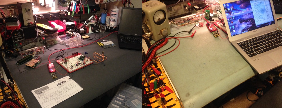
Digikey selected my #digiwish as one of their daily winners! I asked or a new 3M mat for my work bench and it came out looking better than I has hoped for; Thanks Digikey. Unsolicited recommendation: About 90% my breakout boards and specialty items come from Sparkfun or Tindie, but for all my parts and other items such as my Microchip PICkit 3, I shop at Digikey. They have good pricing and a lot of times I get my order the next day with the cheaper shipping despite being half way across the country.
The before and after photo! (left to right it’s actually after and before)
I was a winner of #digiwish from @Digikey this year. I wished for a new mat for my workbench… I knew I wouldn’t buy one myself. Thanks to Digikey my bench has a fresh new look!