I pulled out the weather radio project today to see what I could get done in a few hours. I was pretty close on finishing off the hardware but I fell a little short right at the end. I found I had forgotten to buy something to convert the regulated 5V to 3.3V for the radio (and PIC since they’re tied together on I2C). I ran into a few issues I totally spaced:1. The Si4707 requires a reset after power up .. it ignores I2C if you don’t.
2. Pull-ups.. duh, not only on I2C which I had, but don’t forget the Si4707 reset (oops).
I ended up buying a couple random Digikey parts at the ham radio convention and guess what? 10@ MCP1802T-3002I/OT (300mA 3.0V LDO) ..they are SOT23-5 and I had JUST gotten 10 break-out boards in the mail so I ended up having a 5V3.3V converter (close enough anyways, as the PIC and Si4707 work down to 2.7V).. soldered it up but I didn’t have time to pop it in. I used the Weller but I think I’m going to solder another one with the new hot air gun I got this week. I ordered one of those cheap 858D rework stations; I don’t plan on using it too much so hopefully it’ll do the trick. I also got a bunch of SMD protoboards.. so I get to practice reflow this week.
Tomorrow I should be able to finish up the radio and then it’s all software.
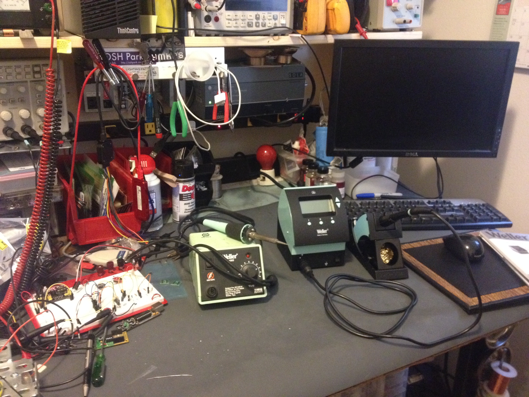
The photo isn’t the most exciting workbench shot but you can see that 858D in the back corner. The WX radio is the black box right up close to the left.
I didn’t have a very productive weekend in the workshop. I received a ton of parts Friday and Saturday including the case to the WX radio. I started installing parts and pieces in the case. I’m always very nervous about the first drill hole.. A only made a minor error (so far) and it is nothing noticeable.
I spent much of the weekend with my wife doing little tid bits outside the house. She spent a lot of time home last week so she was sick of being home; that directly translate into a reduction of bench time 😉 She did go out for a work thing Saturday and I went down to the Mike and Key game radio swap meet. I purchased a bunch of odds and ends and gave up when my pockets were full and I couldn’t carry anymore.
This morning we went out for a quick bit after sleeping in a little and went for a hike out east. It was relaxing but ate up most of the day. I suspect I won’t end up with a lot of bench time until this next weekend: I will likely have a bunch of overtime at work as I just inherited another project when I’m already way overbooked. I know, better than not having work.
Some of my purchases include a cheapo hot air gun.. For reflow soldering. I don’t know if I made a mistake going cheap? I also bought a new power supply and just a ton of parts. I pulled my last 16pin DIP socket out and can’t believe I didn’t order some last time?! How embarrassing! I also ordered six of the new TAUTIC 18F26K22 dev boards on Tindie and some blog stickers.. Check out those dev boards if you’re into PICs, their pretty slick.
I’ll leave you with a photo of the falls we hit up on our hike today…
I was inspired by Alan Wolke’s ( @W2AEW ) video on measuring capacitors and inductors with an oscilloscope. I tried it out and it works pretty reasonably; yeah why wouldn’t it? Anyhow, if you can do it on an oscilloscope it can be done by a microcontroller right? I have been trying to keep myself from buying this $220 eBay LCR meter on eBay.. it looks nice enough (model: MCH2811C). I needed to make this a project or I was going to pull the trigger on some Chinese garbage!
I went with simple and cheap, I don’t know how well it’ll work out yet but I bread-boarded a proof of concept design. It tested okay after some modification. The first road bump was I had found the PIC output pins had unacceptable rise time compared to 74HC14. The first change was using the PIC output to drive the 74HC14 HEX inverter to get the quick rise time needed. I’m throwing a fast edge at the tank circuit that includes an “unknown” inductor and then I do my measurement, just as Alan used his homebrew TDR circuit. I went really low tech on my measurement circuit, I may change this. I used an LM339 comparator and a trimmer as a voltage divider. The first couple waves in the tank “ring” trigger the comparator and I measure the frequency by figuring out the time between the positive pulses by timer. Pretty simple no? It works fine as it turns out. I will have to get a better capacitor and ensure I measure it very accurately to do my math in the PIC and get a reasonable result.
Instead of the usual photos I made another YouTube video. It wasn’t a great one, one take, no editing.. it’s gets my point across (kind of).
My project proof of concept for the PIC L-meter. With the addition of a known inductor and a rotary switch and a little more code you can turn this into a PIC LC-meter in no time.
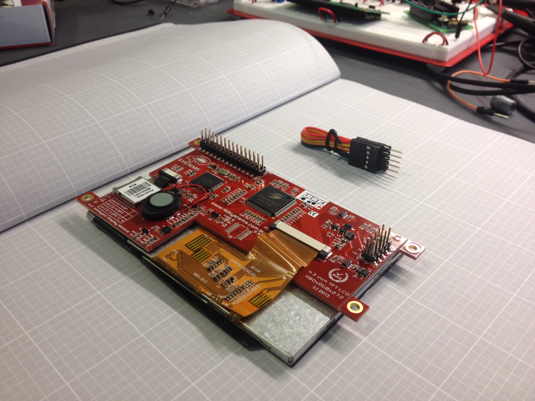
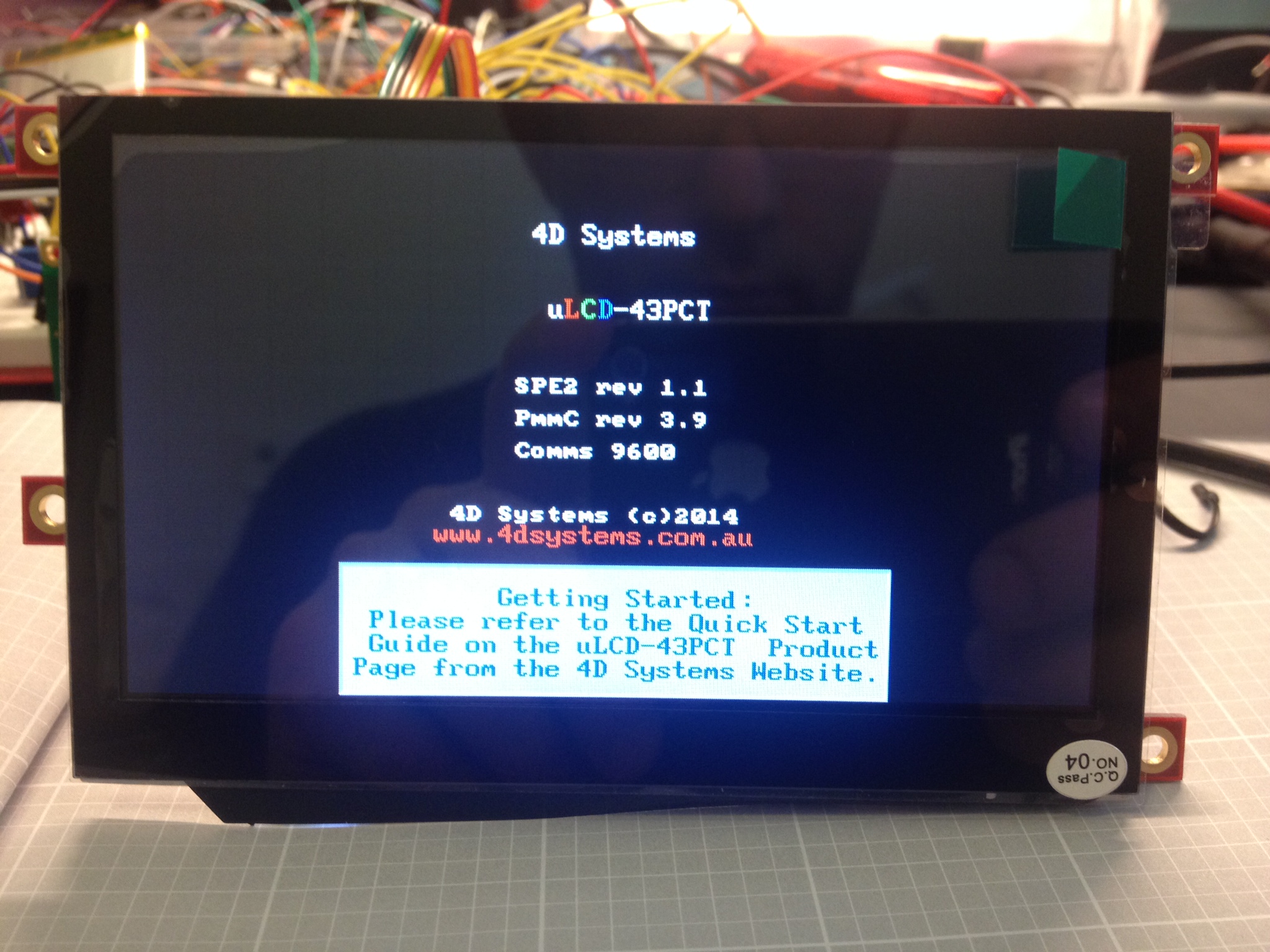
So as suspected the uLCD-43PCT display worked just fine once I got their USB-RS232 dongle.. it has a RST pin.. maybe it uses it in some way when programming? I didn’t do any research because I just wanted to try the display out but maybe I’ll check that out later.
I used Visi Genie which is one of four options you have for configuring their displays. It’s not bad.. but it’s not great. It gives you a very limited number of switches, buttons, numeric displays, etc.. but it worked. I also haven’t found a way to send text to the screen which I can’t believe I couldn’t do.. I just haven’t found it I hope? You can dig in and actually use some of the other configuration modes in which I imagine you can design your own display in detail…again maybe some time I’ll check that out. It’s all code and looks like it would make for a very long day or two. The Visi Genie took me about 3 hours to figure out and configure the display. I ran into a few issues.. of course some of my time was just picking what colors I liked best. The colors show up on the monitor a little different from the LCD so that took some tweaking.. also I noticed the LCD is a little less readable than their simulated display: no big deal though.
The really REALLY annoying bug that took me about an hour to figure out (while was figuring out the serial protocol) was the “LED Digits” module… I dropped it in, selected 6 digits with the decimal place in the third; check, no problem. When testing I could write 1, …. 2, ….3,… WTF? See photo below.
How did that happen? The serial commands were right… after a while I dropped in the Custom LED display.. this next photo shows both displays with “200” written to them.. note: the larger LED segments has the leading zero’s turned off (hidden), it’s setup at six digits.
AARRG!!!?!?!?
…… sigh.
I finally switched my display from 6 to 4 digits as a test (well really 2+4 digits). Success! I guess the program doesn’t like over 4 digits which makes sense because after I figured the serial protocol out there is only room for 4 digits in the packet. Why does the program allow for more than four? The program does a pretty good job of limiting everything else … oh well. It’s finished
The display set up to my satisfaction.
Next steps … I’m deciding if I want to wait for the Tautic 18F26K22 dev board or order something and use one of my protoboards or even just stick with the 16F1509? I’ll figure this out shortly once I decide how I’m going to mash this all up together. I ordered another Si4707 from Richard @ AIW Industries. Hopefully his board is decent: It has promise with the BNC connector and you can buy a fairly cheap Larson whip from him for 12$ and change for the right band which is pretty nice (no more random-wire antenna!). I’ll probably have to shelf this project for a week until it arrives anyhow.
I started up MPLAB 2.05 after the update… I want going to start programming but didn’t get far before I ran into this..
It looks like it marks “TODO” in tasks!!?…. I don’t know if this was an option before but I usually just //TODO if I have something I need to get to… perhaps the update reset some toolbars? I don’t know but I really like this feature. I love me some MPLAB.
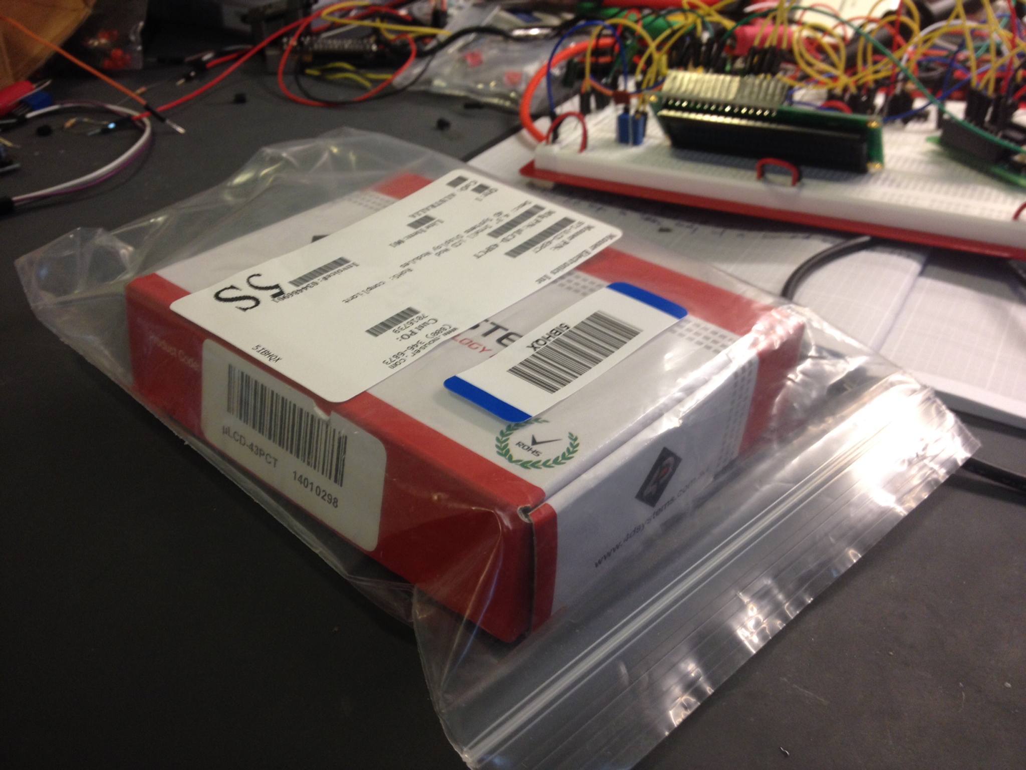
First off, I can point fingers, you can point fingers, who cares.. the fact is I’m pretty underwhelmed by my first day with the “Intelligent LCD”. I purchased the 4D Systems uLCD-43PCT LCD based on a SparkFun YouTube video describing how to use the product and associated software.This product is “intelligent” because it has it’s own processor and serial interface. The idea is to build the interface in software on your PC, drop it on a flash card and program the display.. then just use some simple serial commands to update the display, offloading all that work so I can add this to simple PIC projects with ease. By the p/n you can tell I got the 4.3″ LCD with capacitive touch screen.
I ordered the LCD second day air from Mouser ( @MouserElec ) because they offered the best price I could find. ($190+20) On the YouTube product review, Nick at SparkFun mentioned that he was using the 4D Systems USB to serial adapter because Spark Fun’s doesn’t work and can damage it (due to wiring?). I checked the specs and it says the LCD is 5V tolerant. I used my USB to serial adapter (TTL serial) which works great with PICs as long as they’re 5V tolerant. Well unfortunately, no luck… I can tell the LCD is communicating in some fashion because with a terminal client and with the terminal client built into the “Workbench” software (wasn’t that the name of the Amiga OS?).. in both programs I could enter carriage breaks or other characters and get some serial response from the LCD (usually NULLs (0x00).).. so there is some communication going on.. but the Workbench software itself declares the LCD is not attached. I also confirmed some communication with my logic analyzer. I ordered the 4D systems USB converter from Sparkfun and now I’m back to waiting. How lame.. if you really-really need a specific adapter why not just include it? what is the BOM on something like that? $1-2
I guess I’ll find out in a couple days when my Spark Fun order comes in. I was really hoping to get my display loaded. I spend a few hours on Sunday and Monday tweaking my design… TBC.
I covered the TCN75A i2C sensor a few weeks ago in a simple test to practice using I2C. I had never used I2C before and I knew it was time to stop avoiding it and jump in if I was going to use some of the fun chips and modules. Shortly after posting my results and code I jumped into @tymkrs IRC (visit their site if you’re curious) and Victor ( @vicatcu ) must have at least caught the article subject as he asked me if I noticed the chip runs a little warm (I think he mentioned roughly a deg C?). I had also noticed that oddity myself but I ignored it as I was only concerned with the actual communication. Victor ( @vicatcu ) posed the question: what would happen if I had a vented circuit board? Would that cure the chip from running hot?
Well that was half-brilliant wasn’t it? I had to know! Does under chip venting on the PCB effect temperature readings? I decided to purchase more sensors and SOIC break out boards as well as make sure my Fluke 51 was calibrated.
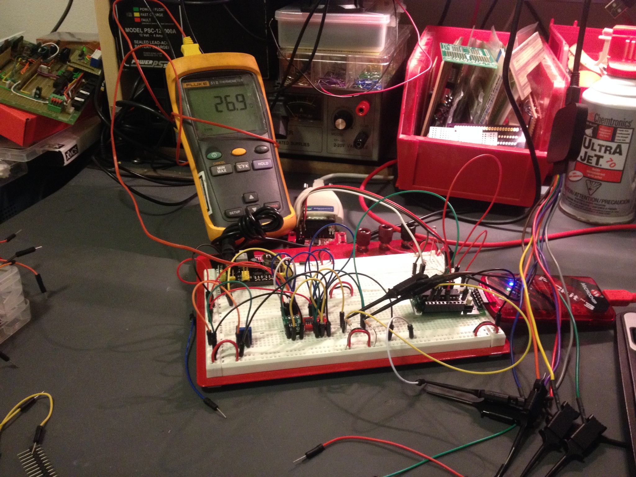
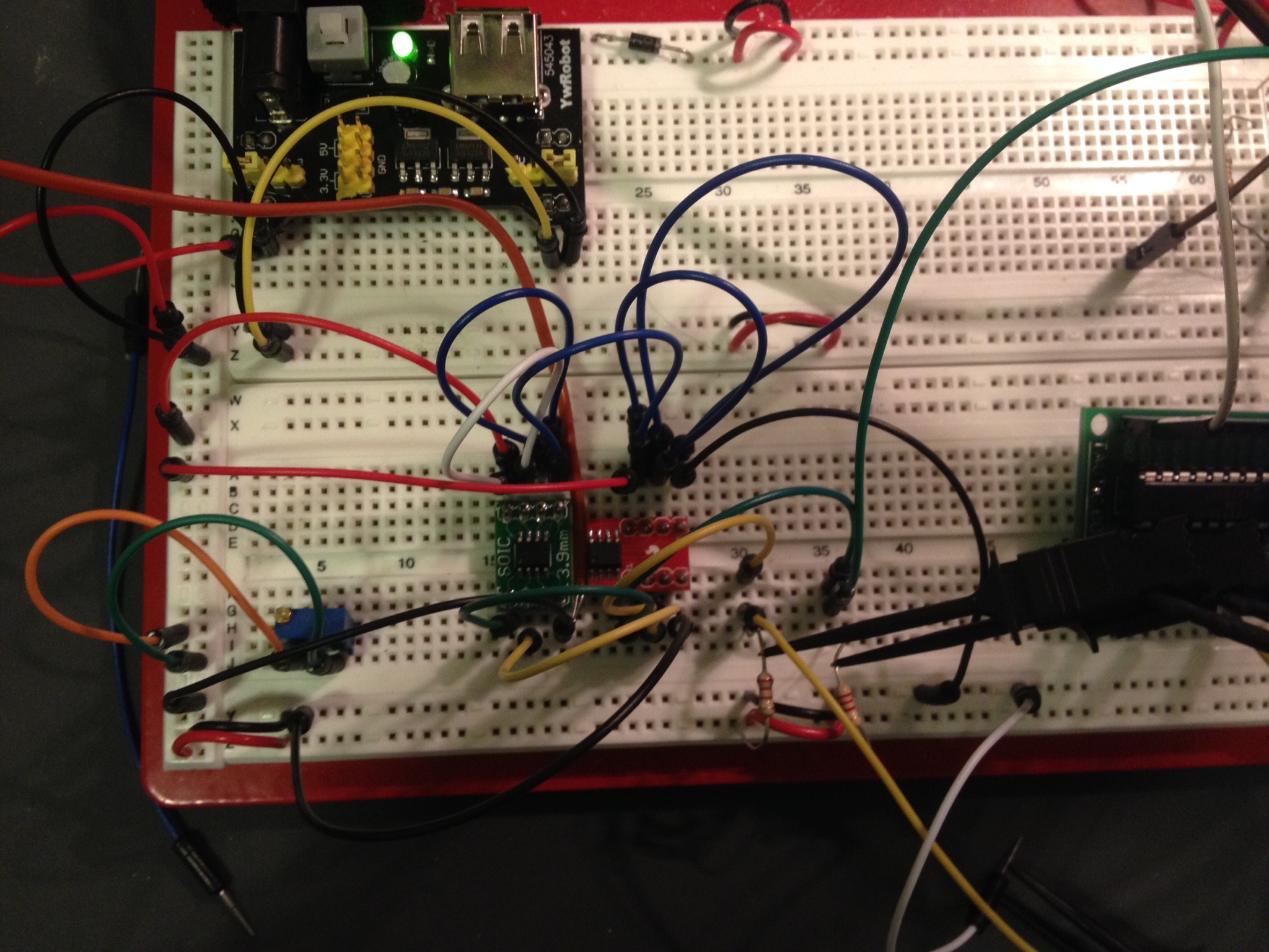
Upon receiving the SOIC breakout boards I took one and carefully used a Dremel to mill out the package outline. I had started to design my own PCB but I abandoned that because I didn’t want to wait for fabrication. I mounted the new sensor on it’s vented PCB then plugged the sensors right next to each other on breadboard and put the temperature probe wedged between the boards. Obviously factors like mounting the sensor near power transistors or near your power supply are always going to have some effect on your readings, and in some cases maybe that’s what your application is meant for. I wanted to take those factors out of the equation. My workshop heating and A/C was off for over a day when I did this test… no windows where open and the chips had been prepped for about 1/2 hour on the board while I wrote the code to test them out. I decided to read data straight from the I2C bus with some confirmation on RS-232 telemetry. I did this in case I introduced any math problem in my conversion in code. I also stuck with Celsius over Fahrenheit because that was the native output of the sensor.
SOIC breakout board with vent cut into itThe setup of the initial test.
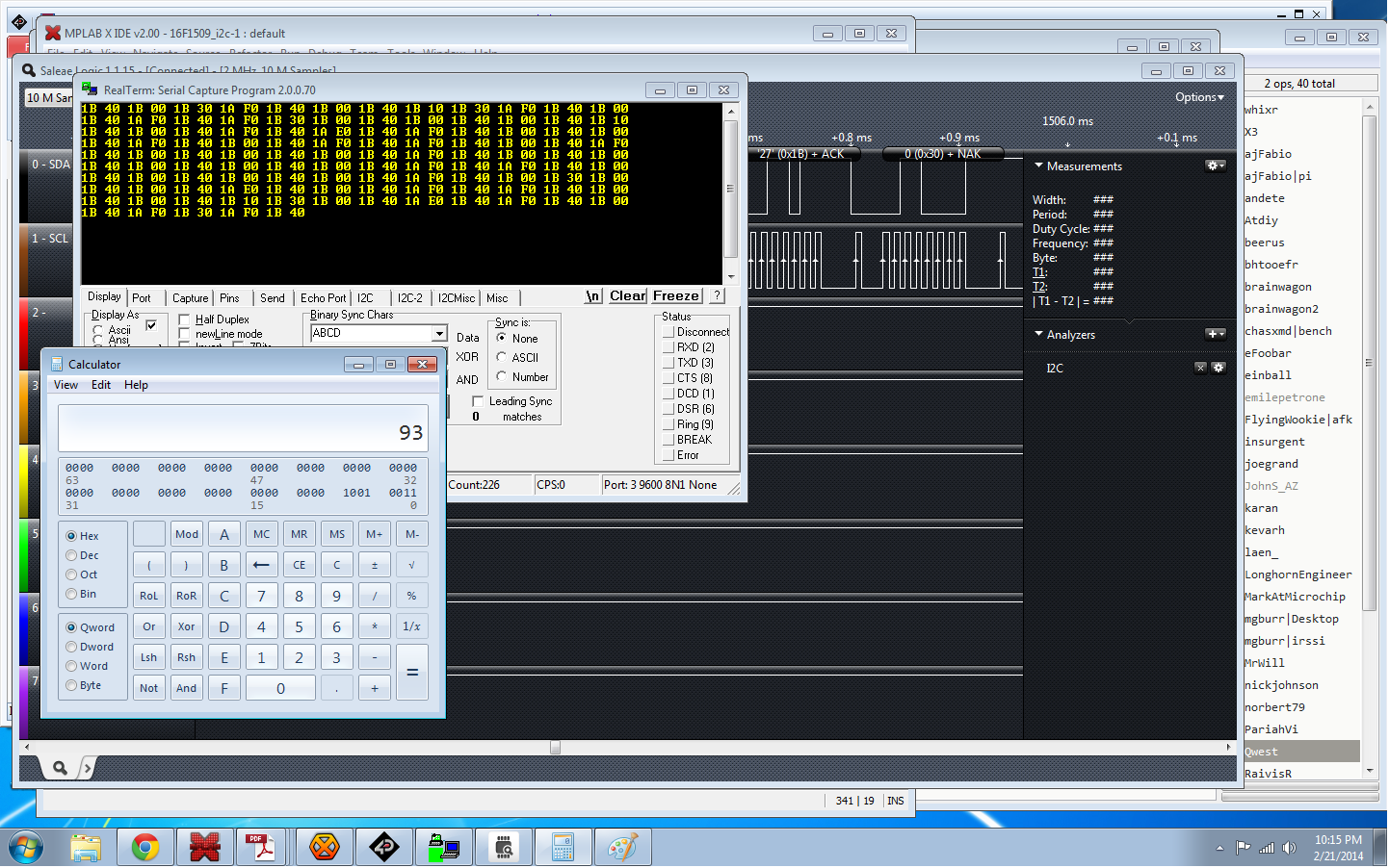
After downloading code and checking everything out my Fluke 51 read 25.8 deg C, the un-vented TCN75A read 26.06 deg C and the vented TCN75A read 25.81 deg C. Over time the un-vented sensor would measure up to 0.400 deg C away from the other two. It’s not 1 deg C but it is something.
Temp sensor telemetry; don’t mind the calculator. I was confirming a hexadecimal I2C address.
Test #2, a muffin fan…. same set up. No real change; roughly the same results.
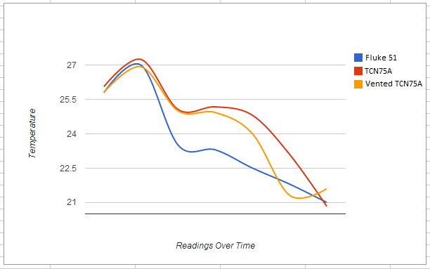
Test #3! What about a change in temperature? I grabbed a cardboard box, put my test circuit and a bowl of ice with some water in the bottom of it, with a muffin fan blowing into the bowl and covered the whole thing in with saran wrap. Not the most insulated thing but I was only looking for a couple degrees. The test proved interesting… both sensors had some lag, and the venting only offered some minor help. It caught up first but they still have a fair amount of lag over the K type probe. In the graph provided I measured at even intervals over 15 minutes. The box settled out at the end (not enough insulation I imagine) the temperature flattened out so I dropped that data.
The Fluke 51 with K type thermocouple vs the normally mounted and modified mounting TCN75A temp sensors.
I can live with the results. I think if I were going to design a board where I wanted as close to an accurate temperature as I could get with this part I would definitely have a milled vent. In hind-sight I would make the vent so it is along the chip axis and protrudes past the edges of the chip. Thanks again to Victor for the great idea!
I’ll get the “other” updates out-of-the-way before talking about my new love! I’ve collected a solid number of PIC development boards over the last couple years and in about 3-4 weeks I’m going to do a review over what I have collected and what I’ve liked and disliked about them. Do you have any suggestions on a board I just can not miss? I am not sponsored, nor do I collect any money from blogging so I’m not going to buy dozens but I’d be willing to buy a few additional boards if someone has been holding off on pulling the trigger on a purchase. I’m not much of a “review” type person but I’m passionate about development boards for prototyping and I would hope my review would help give someone something to think about before purchasing something for their first or second project; PIC based or not. E-mail away!
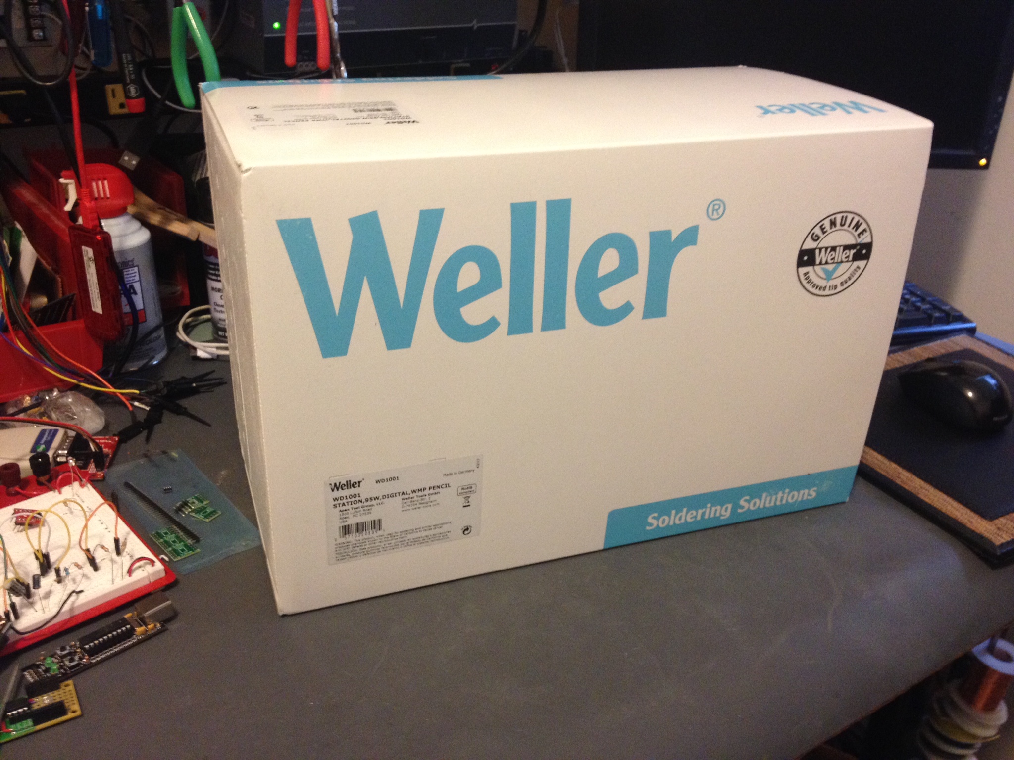
It’s a changing of the guard on my bench. My beloved EC1002 is being replaced by the WD1001. It took me a while to decide on the WD1 platform. I decided on the WD1001 over the WD1002 strictly based on the pencil. The WMP appears to be more helpful for small circuit soldering. The WD1 base is very robust, it could be used as a weapon in a pinch. They cord to the pencil appears like it’s made from something that’s near impossible to tangle and is very flexible. The stand… a dream. The only thing it was missing out of the box was a connector to ground it. There is a base connector attachment which appears to be a 1/8″ mono tip/sleeve audio-type jack. I’ll just have to build something myself. Otherwise I’m in love with the purchase.
@whixr was really trying to sell me on the Hakko FX-888… he is in love with his. I did consider the purchase despite feeling like the blue/yellow made it difficult for me to take it seriously as a tool. They have a new silver version; Perhaps I’ll buy one to test out and send to my brother. I was also seriously considering Metcal.. but after a little I can tell I’ll have no regrets with the WD1002.
Adam Fabio was definitely on team-Metcal and he just about had me sold. It all boiled down to a review of the WD1001 on YouTube and how agile that pencil is.
Check out how close you are to the work with that WMP handle! I really feel in control.
Not the most exciting thing in the world, but a good iron really makes like easier. I put my time in with 25 and 35 watt wall corded pencils. The old radio shack models, even the 35W weller… nothing beats a nice thermostatically controlled station.
The last robot I built was a Roomba Sumo Robot (Talos) for a small competition with co-workers. While collecting parts for this little eBay robot platform I got for somewhere in the neighborhood of 15$USD, I grabbed my Pololu motor controller and remember that I wrote that whole Sumo robot in ASM; that was a lot of code between two PICs.
The little robot I’m building now has very few specifications. It’s goal in life is to follow you around, but not too close. It should back away when needed and basically run around, pausing for a while in its search for someone to follow around. My wife named it Spunk because she’s certain to be the one it annoys most.
I’ve built the project as seen in the photo and written all primary code.. ordered a lot of battery management parts to see what I like the best. Determined I can’t get the robot to “find” people with the sensors I have, so I ordered more… so this little guy is half-done. I’ll shelve him until more parts arrive. I really only grabbed it down as it was 4 projects deep in the to-do list because I haven’t kept up with pre-ordering parts, or worse.. ordered the wrong things. I’m still on the hunt for a better display for the WX radio, ordered items for my RS-485 project, etc. etc..
The heart of Spunk is a PIC 18F14K22 on a TAUTIC 20 pin development board. Maybe Jayson ( @TAUTIC ) needs to pay me for all this advertising? 😉 jk.. I just bought a couple of the boards because they fit my type of prototyping perfectly. This was my last one… time to make an order over at @tindie for some more.
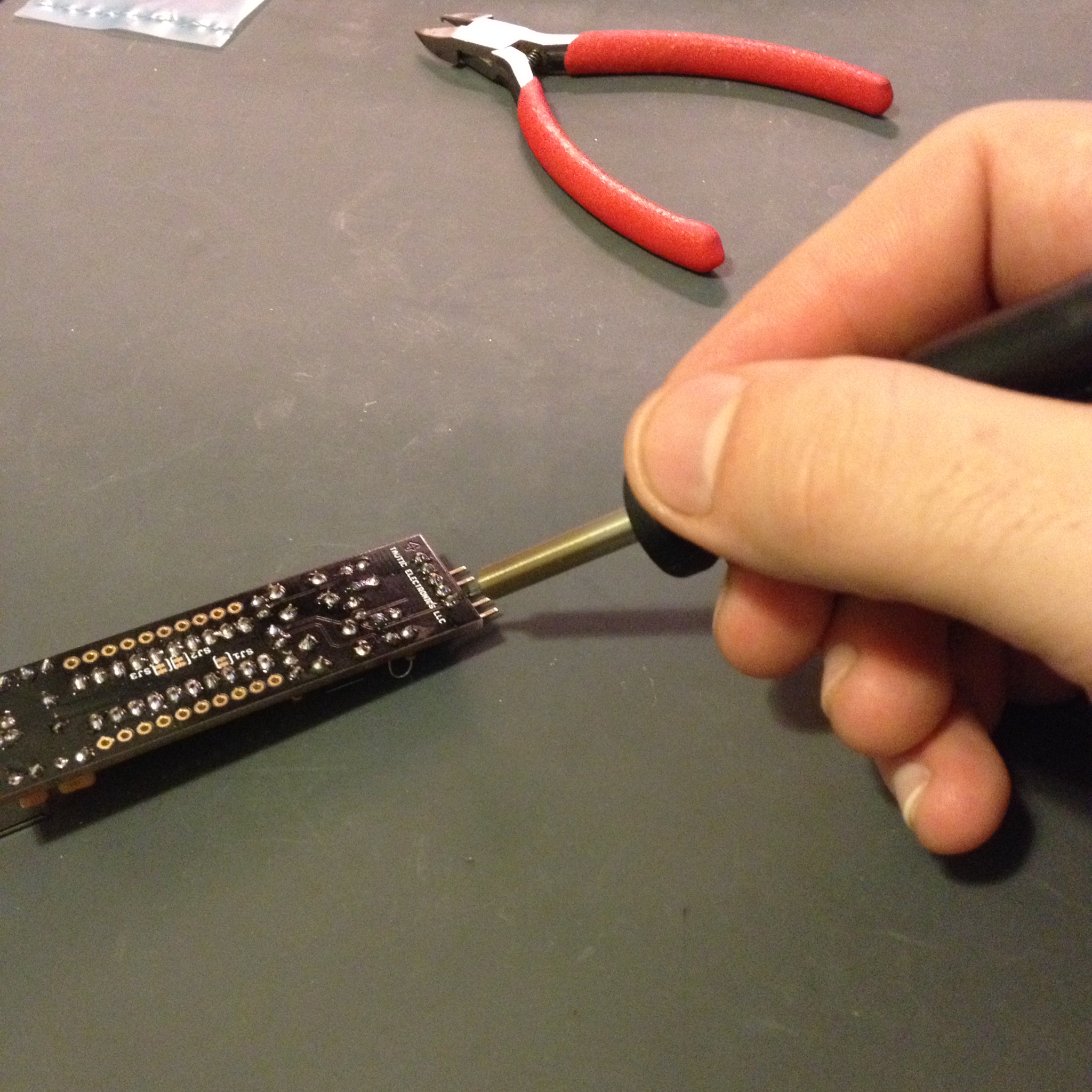
Spunk getting probed.
For now, no code. I’ll post the old ASM code for the Pololu motor controller and the C code as well once it get it properly commented and make sure it at least mostly works. Once I do some real roving tests I’ll throw it on YouTube (and maybe the first tests of Talos as well)… TBC for now.
I don’t want anyone thinking they’re going to see a bunch of music related items on the blog because I’m really no good at such things. My brother on the other hand is very talented and we recently decided he needed some more MIDI toys. A lot of his music is already created with the help of MIDI.
MIDI is “Musical Instrument Digital Interface“; a standard that defines hardware and protocol. If you want more information on it such as specifications Google is your friend.
My brother had some information on the specification but not really anything that helped me much. I did a lot of reading on the specifications on the MIDI Manufacturers Association webpage and then countless other sites describing the protocol in length. It even looks like there is a tutorial on the Arduino site, although I didn’t look at it because I don’t use them. Again, I’m not going to go into the protocol anymore than I discussed the specification. I’ll let you do that leg work. However, the *really* short version is there are a couple key commands followed (usually) by some extra bytes (generally 1 or 2). All the data is transmitted like normal 8N1 serial data at 31.25kbaud. Lucky for me 31.5k has a nice PIC SPBRG division value for low error rate (at 4MHz).
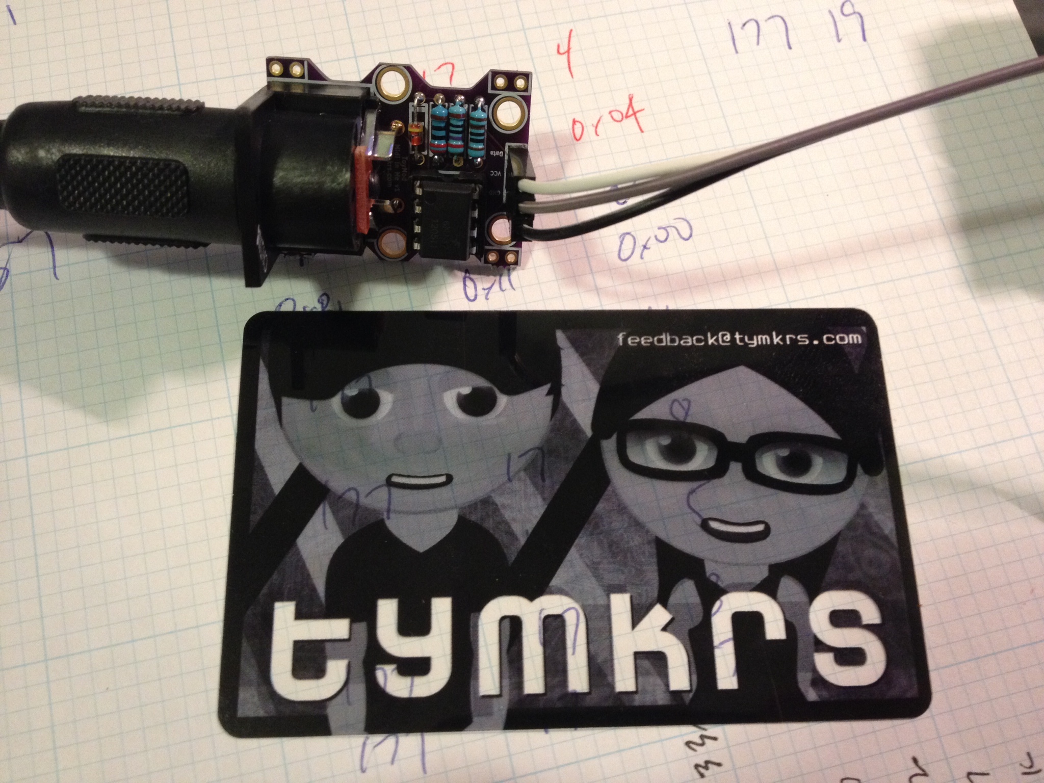
Hardware Interface: I decided I wasn’t going to build the 5mA loop interface and I remembered the Toymakers ( @tymkrs ) had a nice little interface board already built. One trip on over to their Tinde Store and I had it a few days later.
It’s a small kit, it came well packed, and it fit the bill just fine. I have nothing but praise this little kit with only one tiny little nit-picky mention. I wish they included a URL of the location of the instructions for building the kit. They had a couple resistors and I needed to know what was R1, R2, etc.. it was easy to find, a return trip to Tindie linked instructions, a construction video! and a lot of information on their website. So I know I’m picky.. If they wanted to make a 9.7 a 10.. that’d be it 😉
The Toymakers Midi In Me Kit.
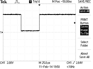
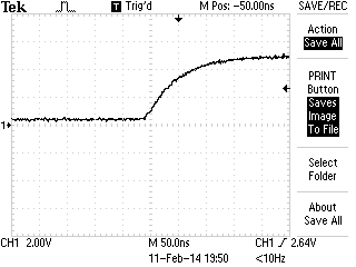
After everything was plugged in, code was loaded on the PIC, a MIDI device plugged in.. etc.. I checked out the MIDI kit to see response and how noisy it might be… no complaints here.. it looked good…
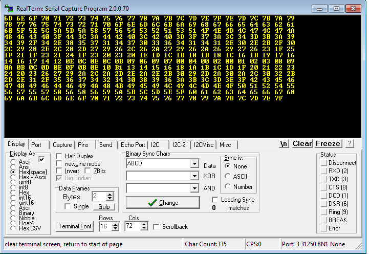
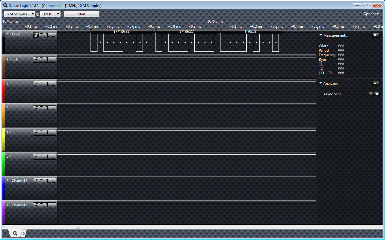
The Firmware: It’s just “sample” code. I haven’t written any real output yet because my brother is in charge of the “analog” bits which really means he is going to figure out what he wants in block diagrams and I will have to figure out how to make it happen in circuit. Right now I’m reading the MIDI signal in on UART by interrupt… and checking for my command signal. (I’m using a Control Change because of my MIDI device… you will most likely want to change this). The control change value is 0xB1 in my case, then… my device (Knob #1) which is 0x11 … and finally it gives me a value (knob position 0x00 to 0x7F). I’m taking that position value and transmitting it out the UART to my PC…
The output dropped onto my PC. Note: RealTerm allows me to enter in 31250 baud.. 8N1MIDI on the LA
I used the TAUTIC 20 pin dev board (any groaning of “AGAIN??”??) … but a change-up! 🙂 I used a PIC 18F14K22 … because I felt like getting crazy 😉 and the 18 series is optimized for C so I will probably go back to the 18F series … I think the last time I used one was my ESR meter? A few changes switching to the 18 series.. but nothing huge. Just getting used to slightly different registers. Last warnings about the code; It’s simple… it’s just checking to see if your interface it working… (or if you’re sending MIDI and you don’t have a scope or LA). It has a lot of clutter because I was using it for some other non-MIDI related testing but it’s easy to spot and delete if you need to copy it as a starting point for whatever you’re working on. (Do share!)
/*
 * File:   main.c
 * Author: Charles M Douvier
 * Contact at: http://iradan.com
 *
 * Created on February 8, 2014, 11:39 AM
 *
 * Target Device:
 * 18F14K22 on Tautic 20 pin dev board
 *
 * Project: MIDI Slave
 *
 *
 * Version:
 * 0.1  Configuration, 31.25Kbaud TX&RX
 * 0.2  Grab MIDI byte from 31.25K MIDI and turn around and TX the value of the
 *      MIDI command. <CMD: Control Change><Device><Value>
 *      <B1><11><value> //my example
 *
 */
#ifndef _XTAL_FREQ
#define _XTAL_FREQ 4000000 //4Mhz FRC internal osc
#define __delay_us(x) _delay((unsigned long)((x)*(_XTAL_FREQ/4000000.0)))
#define __delay_ms(x) _delay((unsigned long)((x)*(_XTAL_FREQ/4000.0)))
#endif

#include <xc.h>
#include <stdio.h>
#include <stdlib.h>
#include <string.h>

//config bits
#pragma config FOSC=IRC, WDTEN=OFF, PWRTEN=OFF, MCLRE=ON, CP0=OFF, CP1=OFF, BOREN=ON
#pragma config STVREN=ON, LVP=OFF, HFOFST=OFF, IESO=OFF, FCMEN=OFF

#define _XTAL_FREQ 4000000 //defined for delay

/*
 * Variables
 */

    long int    decm;           //long temp
    int     tempi;              //temp
    int     i, ilevel;                  //temp
    int     itxdata;            //int RS232 tx data
    char    buf[10];            //buff for iota
    volatile unsigned int uart_data;    // use 'volatile' qualifer as this is changed in ISR

/*
 *  Functions
 */

    void interrupt ISR() {

    if (PIR1bits.RCIF)          // see if interrupt caused by incoming data
    {
        uart_data = RCREG;     // read the incoming data
        PIR1bits.RCIF = 0;      // clear interrupt flag
                                //
    }

}

void uart_xmit(unsigned int mydata_byte) {

    while(!TXSTAbits.TRMT);    // make sure buffer full bit is high before transmitting
    TXREG = mydata_byte;       // transmit data
}

void serial_init(void)
{

    // calculate values of SPBRGL and SPBRGH based on the desired baud rate
    //
    // For 8 bit Async mode with BRGH=0: Desired Baud rate = Fosc/64([SPBRGH:SPBRGL]+1)
    // For 8 bit Async mode with BRGH=1: Desired Baud rate = Fosc/16([SPBRGH:SPBRGL]+1)

    TXSTAbits.BRGH=1;       // select low speed Baud Rate (see baud rate calcs below)
    TXSTAbits.TX9=0;        // select 8 data bits
    TXSTAbits.TXEN = 1;     // enable transmit

    RCSTAbits.SPEN=1;       // serial port is enabled
    RCSTAbits.RX9=0;        // select 8 data bits
    RCSTAbits.CREN=1;       // receive enabled

    //BRGH=1        31.25KHz
    //SPBRG=7

    SPBRG=7;               //

    PIR1bits.RCIF=0;        // make sure receive interrupt flag is clear
    PIE1bits.RCIE=1;        // enable UART Receive interrupt
    INTCONbits.PEIE = 1;    // Enable peripheral interrupt
    INTCONbits.GIE = 1;     // enable global interrupt

         __delay_ms(50);        // give time for voltage levels on board to settle

    //  uart_xmit('S');         // transmit a character example

}

void init_io(void) {
    TRISAbits.TRISA0 = 0; // output
    TRISAbits.TRISA1 = 0; // output
    TRISAbits.TRISA2 = 0; // output
    TRISAbits.TRISA4 = 0; // output
    TRISAbits.TRISA5 = 0; // output

    ANSEL = 0x00;         // no A/D
    ANSELH = 0x00;

    TRISBbits.TRISB4 = 0; // RB4 = nc
    TRISBbits.TRISB5 = 1; // RB5 = nc
    TRISBbits.TRISB6 = 0; // RB6 = nc
    TRISBbits.TRISB7 = 0; // RB7 = nc

    TRISCbits.TRISC0 = 0; // output
    TRISCbits.TRISC1 = 0; // output
    TRISCbits.TRISC2 = 0; // output
    TRISCbits.TRISC3 = 0; // output
    TRISCbits.TRISC4 = 0; // output
    TRISCbits.TRISC5 = 0; // output
    TRISCbits.TRISC6 = 1; // input
    TRISCbits.TRISC7 = 1; // input

}

void set_cmd11(void)
{
    //set an AD output
                while(uart_data==0x11)
            {
                i++; //wait for next char
            }
            ilevel = uart_data;         //finally the value
            uart_xmit(ilevel);
}

void check0xb1(void)
{
    if (uart_data == 0xB1)
    {
            while(uart_data==0xB1)
            {
                i++; //wait for next char
            }
            if ( uart_data == 0x11)     //and the knob 1 is "device 11"...
               set_cmd11();
    }
}

int main(void) {

    init_io();

    // set up oscillator control register, using internal OSC at 4MHz.
    OSCCONbits.IRCF = 0x05; //set OSCCON IRCF bits to select OSC frequency 4MHz
    OSCCONbits.SCS = 0x02; //set the SCS bits to select internal oscillator block

    serial_init();

    decm=30;            //testing

    ltoa(buf,decm,10);  //long conversion to buffer
    tempi=strlen(buf);  //uh, adding leading zeros..
    uart_xmit('+');
    uart_xmit(itxdata);
    uart_xmit('.');
    LATAbits.LATA0=0;

    while (1) {

        i++;

        while (uart_data)
        {
            check0xb1();    //my midi device is sending a Control Change 0xB1
            uart_data=0;
        }

    }
    return (EXIT_SUCCESS);
}