PIC 16F1509 NCO code sample

I didn’t read a forum post all the way through (or maybe I was just tired) and I accidentally responded to question about PWM; however the question was specifically about using the numerically controlled oscillator (NCO). I decided to take a look at this module and wrote some quick code. I also have been testing hardware for isolating PWM signals… so I married them together despite not being how I would use this in a real world application.

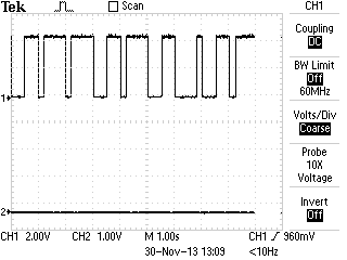
The NCO code worked great and was easy to set up. I used a simple loop to have it sweep a frequency… dumped the output of NCO1 (RC1) into a optoisolator which originally I was driving it way to fast… well unfortunately my isolation circuitry wasn’t quite up to the challenge of the speed but in the lower end of my sweep I got adequate results and ultimately the NCO test was very successful. While I was reading up on the NCO in the 16F1509 manual I started reading the configurable logic cell (CLC) module section. What a surprise to find this block in a 16F series microcontroller! The CLC is definitely going to get some more attention from me in the future. As always sample code follows below…


I had answered a question about a PWM signal a while back and responded with some PWM code ... well I didn't read it all and they were wanting to use NCO. I hadn't used it... so I just hacked some stuff together to check it out.
I had answered a question about a PWM signal a while back and responded with some PWM code … well I didn’t read it all and they were wanting to use NCO. I hadn’t used it… so I just hacked some stuff together to check it out.


So the important stuff! The code written for the Microchip XC8 compiler:

No warrantee and don’t assume it’s free of bugs. It free to steal; enjoy. Code fix recommendations in the comments please.

Download: 16F1509_NCO.c

* File: main.c
 * Author: Charles M Douvier
 * Contact at: http://iradan.com
 *
 *
 * Target Device:
 * 16F1509 on Tautic 20 pin dev board
 *
 * Project:
 *
 *
 * Version:
 * 1.0
 *
 */
#ifndef _XTAL_FREQ
#define _XTAL_FREQ 4000000 //4Mhz FRC internal osc
#define __delay_us(x) _delay((unsigned long)((x)*(_XTAL_FREQ/4000000.0)))
#define __delay_ms(x) _delay((unsigned long)((x)*(_XTAL_FREQ/4000.0)))
#endif
#include <xc.h>
#include <stdio.h>
#include <stdlib.h>
#include <string.h>
//config bits
#pragma config FOSC=INTOSC, WDTE=OFF, PWRTE=OFF, MCLRE=ON, CP=OFF, BOREN=ON, CLKOUTEN=OFF, IESO=OFF, FCMEN=OFF
#pragma config WRT=OFF, STVREN=OFF, LVP=OFF
#define _XTAL_FREQ 4000000 //defined for delay
int count;
/*
 *
 *
 *
 * NCOxCON: NCOx CONTROL REGISTER
 * bit 7 NxEN: NCOx Enable bit
 * 1 = NCOx module is enabled
 * 0 = NCOx module is disabled
 * bit 6 NxOE: NCOx Output Enable bit
 * 1 = NCOx output pin is enabled
 * 0 = NCOx output pin is disabled
 * bit 5 NxOUT: NCOx Output bit
 * 1 = NCOx output is high
 * 0 = NCOx output is low
 * bit 4 NxPOL: NCOx Polarity bit
 * 1 = NCOx output signal is active low (inverted)
 * 0 = NCOx output signal is active high (non-inverted)
 * bit 3-1 Unimplemented: Read as ‘0’
 * bit 0 NxPFM: NCOx Pulse Frequency Mode bit
 * 1 = NCOx operates in Pulse Frequency mode
 * 0 = NCOx operates in Fixed Duty Cycle mode
 *
 * NCOxCLK: NCOx INPUT CLOCK CONTROL REGISTER
 * bit 7-5 NxPWS<2:0>: NCOx Output Pulse Width Select bits(1, 2)
 * 111 = 128 NCOx clock periods
 * 110 = 64 NCOx clock periods
 * 101 = 32 NCOx clock periods
 * 100 = 16 NCOx clock periods
 * 011 = 8 NCOx clock periods
 * 010 = 4 NCOx clock periods
 * 001 = 2 NCOx clock periods
 * 000 = 1 NCOx clock periods
 * bit 4-2 Unimplemented: Read as ‘0’
 * bit 1-0 NxCKS<1:0>: NCOx Clock Source Select bits
 * 11 = NCO1CLK pin
 * 10 = LC1_out
 * 01 = FOSC
 * 00 = HFINTOSC (16 MHz)
 * Note 1: NxPWS applies only when operating in Pulse Frequency mode.
 * 2: If NCOx pulse width is greater than NCO_overflow period, operation is undeterminate.
 *
 */
int main(void) {
 // set up oscillator control register, using internal OSC at 4MHz.
 OSCCONbits.IRCF = 0x0d; //set OSCCON IRCF bits to select OSC frequency 4MHz
 OSCCONbits.SCS = 0x02; //set the SCS bits to select internal oscillator block
 OPTION_REGbits.nWPUEN = 0; // enable weak pullups (each pin must be enabled individually)
TRISCbits.TRISC0 = 0; // output
 TRISCbits.TRISC1 = 0; // NCO1
 TRISCbits.TRISC2 = 0; // output
 TRISCbits.TRISC3 = 0; // output
 TRISCbits.TRISC6 = 1; // input
 TRISCbits.TRISC7 = 1; // input
ANSELC = 0x00; // all port C pins are digital I/O
NCO1INCH = 0x00; // has to be set before INCL
 NCO1INCL = 0x4F; // low accumulator register
NCO1CLK = 0xE1; // 0xE1 = PW 128 clk 0x41 [010][000][01] 8 CLK PER, INT OSC,
 NCO1CON = 0xE1; // Enable, Ouput On, PWF Mode
count = 0;
while(1)
 {
 count = count+1; //just a little test code
 if (count < 1) //LED didn't like the low freq
 count=10;
 NCO1INCH = 0x00; //has to be set before INCL
 NCO1INCL = count;
 __delay_ms(50);
 }
 return (EXIT_SUCCESS);
}


Testing an LCD with the PIC 16F1509 and the XC8 compiler

Nuts and Volts, January 2014 had an article named “The (Nearly) Universal Process Monitor”. The whole magazine had a number of Microchip PIC based articles which is rare these days, as the articles win out to other platforms such as MSP430, Propeller, and Arduino. The article is a pretty nice project but I went to download the code and it’s just a HEX file. Lame! I’ve been guilty of this and I promise never to do it again.

If you’re as disenchanted with building something without modifiable code as I am here is a starting block! I don’t normally program in C but I’m trying to force myself so I can get better. You can trim down many timing delays, and certainly shouldn’t be a problem to optimize my code as I made no effort to do so myself.

LCD+A/D test on the PIC


When writing the A/D math for this I found some interesting issues; here is one of those: (in pseudo code)

int_Var1 = 8-bit A/D conversion
long_int_Var2 = int_Var1 * 5000

given int_Var1 = 17  long_int_Var2 should equal 85000 but it didn’t; It came out 19,464 (roll over from 65,536).

However:

long_int_Var2 = int_Var1
long_int_Var2 = long_int_Var2 * 5000  //works like a charm.

Weird? I tried this in an ANSI C compiler and the first equation worked okay; I guess this is just a quirk about XC8. I somewhat understand why it would act that way and caught it quick but it could easily have been a difficult bug to hunt down.

There is obviously not the greatest amount of resolution in an 8-bit conversion but I was really just testing an LCD I just got off eBay and through this would be a fun way to do so, work on my C skills, and help out anyone wanting a head-start on building their own metering application. If you don’t want to do the math yourself you’ll find you get about 20mV/step resolution (5000mV/256) at 8-bit.


The thousands position is moot and could be dropped. The resolution of the A/D being used in 8-bit doesn't allow for reliable usage in the thousandths.
The thousands position is moot and could be dropped. The resolution of the A/D being used in 8-bit doesn’t allow for reliable usage in the thousandths.


Notes: Refresh is slow, clearing the LCD line #2 is slow because I didn’t like the flash of clearing the whole display… it could have also been made more quick had I not written 16 spaces and just written enough to cover my 7 digits of output. I also should have dropped the LSB of my number because it’s a worthless bit considering my resolution. I will if this gets used on anything other than a breadboard test.

I used a standard 44780 16×2 LCD, a Tautic development board, and a PIC 16F1509 (happens to come with the dev board). For programming I used MPLAB X IDE v1.95 and XC8 v1.21 (free version) and the PICkit 3 programmer. The code is commented enough to figure out the hardware setup.

code (with whatever fixes since wiring the blog) can be found at : https://github.com/chasxmd/iradan.com-2014

at writing it looks like:

/* 
 * File: main.c
 * Author: Charles M Douvier
 * Contact at: http://iradan.com
 *
 * Created on January 18, 2014, 9:42 AM
 *
 * Target Device:
 * 16F1509 on Tautic 20 pin dev board
 *
 * Project:
 * A/D --> LCD Test
 * 8-bit resolution across Vdd to Vref (0-5V)
 * for 3.3V operation adjust A/D math
 *
 * LCD (44780 type) Test with XC8 compiler
 * LCD code ported from Mike Pearce's 2001 LCD code for HI-TECH C
 * as found on http://www.microchipc.com/
 */
#include <xc.h>
#include <stdio.h>
#include <stdlib.h>
#include <string.h>
#include <plib.h>
//config bits
#pragma config FOSC=INTOSC, WDTE=OFF, PWRTE=OFF, MCLRE=ON, CP=OFF, BOREN=ON, CLKOUTEN=OFF, IESO=OFF, FCMEN=OFF
#pragma config WRT=OFF, STVREN=OFF, LVP=OFF
#define _XTAL_FREQ 4000000 //defined for delay
int an9_value; //value for a/d
 char buf[10]; //buff for iota
 long int fvar; //long for format math
 long int ones; //left of decm
 long int decm; //decimal places
 int tempi; //to add leadign zeros..
/*
 * LCD RS LATA.5
 * LCD EN LATA.4
 * LCD DATA4 LATC.0
 * LCD DATA5 LATC.1
 * LCD DATAT6 LATC.2
 * LCD DATA7 LATC.3
 * LED LATA.0 for scan rate/heartbeat
 */
void lcd_strobe (void) //TOGGLE LCD_EN
{
 LATAbits.LATA4 = 0;
 __delay_ms(20);
 LATAbits.LATA4 = 1;
}
/* write a byte to the LCD in 4 bit mode */
void lcd_write(unsigned char c)
{
 LATC = c >> 4;
 lcd_strobe();
 LATC = c;
 lcd_strobe();
 __delay_us(100);
}
/*
 * Clear and home the LCD
 */
void lcd_clear(void)
{
 LATAbits.LATA5 = 0;
 lcd_write(0x1);
 __delay_ms(2);
}
/* write a string of chars to the LCD */
void lcd_puts(const char * s)
{
 LATAbits.LATA5 = 1; // write characters
 while(*s)
 lcd_write(*s++);
}
/*
 * Go to the specified position
 */
void lcd_goto(unsigned char pos)
{
 LATAbits.LATA5 = 0;
 lcd_write(0x80+pos);
}
/*
 * Write 16 spaces on LCD 2 to avoid blanking, (ugly CLEAR effect)
 * this is slow but work for my needs
 */
void lcd_clrline2(void)
{
 lcd_goto(40);
 lcd_puts(" ");
 lcd_goto(40);
}
/* initialise the LCD - put into 4 bit mode */
void lcd_init(void)
{
 LATAbits.LATA5 = 0; // write control bytes
 LATC = 0x03;
 __delay_ms(150); //power on delay
 lcd_strobe();
 __delay_ms(5);
 lcd_strobe();
 __delay_ms(5);
 lcd_strobe();
 __delay_ms(5);
 LATC = 0x02; // set 4 bit mode
 __delay_ms(5);
 lcd_strobe();
 __delay_ms(5);
 lcd_write(0x28); // 4 bit mode, 1/16 duty, 5x8 font
 lcd_write(0x08); // display off
 lcd_write(0x0C); // display on cursor+blink off
 lcd_write(0x06); // entry mode
}
int main(void) {
 // set up oscillator control register, using internal OSC at 4MHz.
 OSCCONbits.IRCF = 0x0d; //set OSCCON IRCF bits to select OSC frequency 4MHz
 OSCCONbits.SCS = 0x02; //set the SCS bits to select internal oscillator block
TRISCbits.TRISC0 = 0; // output
 TRISCbits.TRISC1 = 0; // output
 TRISCbits.TRISC2 = 0; // output
 TRISCbits.TRISC3 = 0; // output
 TRISAbits.TRISA0 = 0; // output
 TRISAbits.TRISA4 = 0; // output
 TRISAbits.TRISA5 = 0; // output
 TRISCbits.TRISC7 = 1; //analog input
 ANSELCbits.ANSC7 = 1; //...setup on PORTC.7/AN9
 LATAbits.LATA0 = 0; //LED Im-Alive test
__delay_ms(250); //let the power settle
lcd_init();
 __delay_ms(10);
 lcd_clear();
//display test message
 lcd_puts("Testing the LCD.");
 lcd_goto(40);
ADCON0 = 0b00100101; //select AN9 and enable
/* ADCON1
 * bit 7 ADFM: ADC Result Format Select bit
 * 0 = Left justified. Six Least Significant bits of ADRESL are set to ?0? when the conversion result is loaded.
 * bit 6-4 ADCS<2:0>: ADC Conversion Clock Select bits
 * 110 = FOSC/64
 * bit 3-2 Unimplemented: Read as ?0?
 * bit 1-0 ADPREF<1:0>: ADC Positive Voltage Reference Configuration bits
 * 00 = VREF+ is connected to VDD
 */
 ADCON1 = 0b01100000; //left justified, FOSC/64 speed Vref=Vdd
while(1)
 {
 LATAbits.LATA0 = 0; //debugging

 lcd_clrline2(); //clear LCD line 2 by writting " " and return
__delay_us(5); 
 GO = 1;
 while (GO) continue; //wait for conversion
 an9_value = ADRESH; //AN9 value
 //format value for LCD read out
 //value = AD_value * 5000 (because 5000mV is Vref)
 //value = value / 256 (8 bit number)
 fvar = an9_value;
 fvar = fvar * 5000;
 fvar = fvar / 256;
 ones = fvar / 1000;
 ones = ones % 10;
 decm = fvar % 1000;
LATAbits.LATA0 = 1; //LED Im-Alive test. I made it through conversion
//page 366 of XC8 user guide
 itoa(buf,ones,10); //int conv to buffer
 lcd_puts(buf); //outputs "1s" place to LCD.
 lcd_puts(".");
 //page 374 of XC8 user guide
 ltoa(buf,decm,10); //long conversion to buffer
 tempi=strlen(buf); //uh, adding leading zeros..
 tempi=3-tempi; //probably a better way of doing thing
 while (tempi) //first figure out how many zeros
 {
 lcd_puts("0"); //missed 3-string length
 tempi=tempi-1; //then send them until done
 }
 lcd_puts(buf); //output buffer to LCD
lcd_puts(" V"); //attach some units for display
 //delay
 __delay_ms(999); //LCD refresh rate
 }
 return (EXIT_SUCCESS);
}

Quickstart guide to a basic PIC based robots – Part 1

While browsing for “goodies” on eBay I ran across a $9 robot chassis. How can you go wrong for $9? I haven’t built a robot since Talus my sumo Roomba, so I thought why not.

If you’re looking for something like the model I purchased, check out eBay and do a search for “Robot Chassis”.  Adam Fabio of TheRegnineer.com mentioned he has almost completed working on a product that is similar. I’m guessing you can look for Adam’s product at his Tindie Store once he has finished it.

.. Fast forward three weeks for shipping from China.

None of my sensors have arrived but you’ll end up wanting to customize you robot for whatever sensor pack you are interested in anyhow. With that said I haven’t written any code for handling any sensors and at the end of the day this robot is just going to drive straight forward all day long. You can follow the code at the repository I set up for it on github to get the latest updates at…

The software:

https://github.com/chasxmd/16F1509_Rover_Robot

The hardware:

I’m using the TAUTIC 20 pin PIC development board as it’s only $10 and takes care of the reset switch capacitor and comes on a nice plug-in board if you solder the connectors the same way I did. Use whatever you like but notice I’m using an internal oscillator so you don’t have to worry about getting a specific development board or having a crystal.

I’m also using the Pololu Quick 2s9v1 Dual Serial Motor Controller which is cost me $25, a little on the high side, but I had one from another project so I’m just re-using it and it makes life a lot easier for development.

Check out the photo at the bottom of the post for the basic schematic.

Beginners:

If you don’t already have MPLABX you’re looking at an upwards battle. However if you don’t mind watching a few YouTube videos it’s not up a creek.

1. Download and install MPLABX and the HI-TECH C compiler.

2. Start a project within MPLABX; selecting PIC 16F1509 and choosing the HI-TECH compiler, and create a main file.

3. Copy my code off the github site and drop it into your main file and compile.

You can download the free version of HI-TECH C and MPLABX which is also free. They are both obtained from http://www.microchip.com. MPLABX is an IDE (integrated development environment) which means it’s a program for programming, compiling and loading your software. HI-TECH is a C compiler which works with MPLABX. There are other programming language options such as BASIC and even assembly (I use assembly most of the time). I don’t know of any free BASIC compilers but I’m guessing someone has one. Google might be your best friend if  you’re looking to go that route.

If you don’t have MPLABX you probably don’t have a PICKit 3 (or other hardware programming tool). I like the PICKit 3 because it will program all the newer Microchip PICs and it’s just about the most affordable tool for PICs. PICKit3 comes from Microchip or Digi-key. There are alternatives.

The Build:

It took me about 30 minutes to put the chassis kit together last night. It was pretty obvious how it went together which was good because there were no directions. The encoder wheels don’t really attach other than compression, I see issues with that if I end up using them… that’s what you get for $9?

The code I put together this morning in about an hour or two after reviewing the manual for the motor driver online; you should also review this document. The idea with the code was just to test the motors and motor driver. I also selected a high/half/normal speed which you can adjust for your motor’s needs. I believe the highest speed setting you can select is 0x7F, I chose 0x4F for my high speed based on my anticipated desire. Adjust as needed.. but keep in mind your low speed should be set so it doesn’t stall on carpet or whatever you want your robot to be driving around on.

That’s about it for now. Once I get some sensors in I’ll add them and then write the code. I’m still new to C programming but I felt it was a better choice since it seems most popular; I usually write everything in assembler. Check out the photo I posted as it has a basic layout of the circuit and how I set mine up on a breadboard until I receive some prototyping PCBs I ordered.

First step of my cheap chassis robot build... getting the motors turning.
First step of my cheap chassis robot build… getting the motors turning.


…. to be continued

Wireless Plant Soil Monitoring: The Beginning.

I saw a little probe for monitoring soil on eBay.. $1.69 and free shipping.. purchased! Okay.. its a lame little PCB with some electronics I won’t use but still, nifty. I didn’t have much on my plate today and I was pretty sore from a solid hike yesterday so I was riding the bench seat today. I built a little front end circuit mated to a little MCU built on a Jayson Tautic 8 pin dev board with a 12F1840. It dumps serial out to a $3 433Mhz transmitter when the soil is low on water (still need to write some sleep code).. on the other side the receiver and well I don’t know yet. Honestly I started with thinking about a XPORT but I haven’t made my mind up.

Work in progress.... watching dirt dry.
Work in progress…. watching dirt dry.


So, a funny side effect: My wife was frustrated that she couldn’t get our wireless Christmas lights to turn on. Heh, well “Ooops!”… shocker, I had to turn my circuit off. So next I’ll work on the receiver side. I’m thinking my poor plants need to text message me when they’re thirsty? I’ll drop code later when it’s more complete.

And yesterday! I hiked past this pretty awesome frozen water fall (and two others) on my way up to Lake Serene. Last year we got stopped by a nasty avalanche field.. this year is was just solid ice. Thankfully I had my Kahtoolas.

forwa

WWVB Time Signal Generator Test w/ HEX

[Edit: I’ve added the .asm code in the “Code” page in the menu above. Below you can find the .HEX file for easy programming]

A successful test on my WWVB signal generator. I’m going to shy away from calling it a transmitter because I don’t think there is any allowances for any broadcasting on 60KHz, so to stay legal I would imagine you’d need to conform to part 15, shield everything, use an attenuator and dump the signal into a shielded box with the clock? I somehow doubt the FCC checks up on sub-mW transmissions on 60KHz though.

The concept is simple, 1 baud rate transmission of a 60 frame packet. The amplitude shift keying (ASK) system WWVB transmits is recreated using a CMOS CD4066 switch. Dump a 60KHz sine wave (keeping in mind maximum input/output signal specifications) into one of the switch ports. Use the output on PORTB.0 of the PIC to control the switch and the other side of the switch goes to you device under test (I used a couple feet of wire as an antenna and just placed the wire in the neighborhood of the clock receiver). It’s a no brainer. Check out the NIST site on WWVB if you want more details. I’ll probably re-port the code to a 12F629 when I get my new PICKit3 in and I’ll likely build a board with a 60KHz generator.. maybe I’ll even sell it on Tindie if I’m feeling ambitious.

The Test! I was getting my ass kicked earlier this week as my circuit was not working and it seemed like everything was just right. It did force me to really tweak my timing to make it within my range of error on being able to measure the exact pulse widths, I don’t know how precise it has to be but I assume that’s up to the algorithm decoding the signal. Turns out it wasn’t my code or circuit.. My $15 Fred Meyer “black friday special” atomic clock doesn’t work. It won’t receive the real WWVB (set up aligned with Boulder, CO away from electronics, blah blah). I was getting the proper signals out of the module, so I yanked the module out of the clock and hooked it up to a receiver designed by N0QBH. I mirrored his project here. He has a website for the project here. I used his schematic, ditched the need for the LCD and just grabbed my data off the RS232. Done! You can see a before and after output screenshot in the photos below.

My WWVB signal generator code (HEX) for a 16F628A is found here . Is it lame of my just to provide the HEX? yeah…. but all you need to do is hook up PORTB.0 to switching input of a 4066 with a signal generator feeding a 60KHz sine wave and you’re in business. (And a resistor pulling /MCLR (PORTA.5) up as well if that wasn’t obvious? I’m using the internal oscillator; no xtal needed).  You are stuck with my fixed date of course.. which is why you want my assembly code right? No problem. Just ask… really (comment or e-mail). I don’t want to post it because I don’t really like comment trolls. This code is super BETA but at an acceptable starting point. Lots of opportunity for optimizing it as well.  Why didn’t I improve on this code? Because I don’t need to. I’m just using it to test receivers I’ve purchased from the UK and I’ll be working on a project with those in a little while.

My time/date is static here is a snippet of the main line code:

    CALL    MARKER                      ;MARKER FRAME REFERENCE BIT
    CALL    ONE                         ;40min
    CALL    ZERO                        ;20min
    CALL    ZERO                        ;10min
    CALL    ZERO                        ;Reserved
    CALL    ZERO                        ;8mins
    CALL    ZERO                        ;4mins
    CALL    ONE                         ;2mins
    CALL    ZERO                        ;1mins
    CALL    MARKER                      ;MARKER 1

… and so for some photos

signal from PIC before ASK modulation accomplished by switching a CMOS CD4066 with a 60KHz sine wave from a frequency generator.


WWVB receiver module removed from clock

The clock with the module removed, luckily they printed the pin diagram on the board. 5V, Gnd, PON, and TCO

WWVB Signal Generator and Receiver on Breadboard

Both the generator and receiver on the breadboard. The transistors form the RS-232 driver for the receiver.

Before and after on the RS232 output of the WWVB receiver


WWVB Transmitting Generator/Simulator

[Edit: a follow up post includes code]

I owe it to my PICKit3 to give it a proper obituary.

PICKit3-BUR123467218, 1, Side-kick PIC programmer worked long and faithful.  Assisted in countless re-downloads to facilitate troubleshooting poorly written software.  PICKit3 met it’s maker when inadvertently electrocuted with 12VDC. Leaves behind distraught hobbyist programmer companion. You’re gone but not forgotten.

I was finishing up final touches on a 16F629 8 pin PIC that was generating a WWVB broadcast to have a piece of test equipment which will help me write code to receive WWVB ASK time/date information. I accidentally plugged my breadboard into 12VDC. Even with ninja speed I couldn’t get it unplugged in time. The 16F629 and PICKit3 were dead in milliseconds. I had to dig out the PICKit2 to save my weekend. Turns out the only PICs I have that will work with the 2 is a PIC16F628A and a 18F452. So I ported the code to the F628A and tested away on it. I have the code down to what I think is nearly perfect, with nearly perfect timing. I have tapped into the TCON output of a 15$ atomic clock I purchased recently. The clock I receiving the data fine, but it won’t sync for some reason. Two nights in a row with no synchronizing to the actual WWVB so I’m wondering if my 15$ clock just doesn’t work.

I’ll post the code later when I am sure it works. The receiver is on its way from the UK. That’ll be a project sooner than later. I was considering making a breakout/dev board out of the generator but then I saw a seller on Tindie has done that but also married it with a RTC.

The programming for the WWVB was pretty straight forward. Just look it up and capture it from NIST, no reason to repost, but here is a link to the PDF.

EDIT: Ugh, I got retweeted a few times so now I have that I-didn’t-post-code guilt. *IF* you want the code: comment, tweet or e-mail..  I’ll give it to you. I don’t want to post it for free download until I know for certain it’s reliable. I hate to steer someone wrong. Let me know if you want the .HEX file or just the assembly file and you can compile it yourself. I’ll even consider pre-programming a 16F series PIC if you really want it.

Right now the 60KHz transmitter is a function of my signal generator but the parts are on the way to build a solid low power transmitter. Anyone interested in the whole thing on a PCB?

My new PICKit3 and a couple goodies are already ordered along with some goodies…midweek until I can get back to work I suppose.

“To be continued”.

TYMKRS Rotary Encoder + TAUTIC 20 Pin Dev Board PIC Test/Code

I got an order from Tindie last night. I had issues with my DIY stepper based rotary encoder so when I saw TYMKRS “Turn Me v1” kit I had no hesitation parting with $10. It seemed to only come with Arduino sample code so I wrote my own code. My code is written in assembly for the PIC because that’s my preferred microcontroller and I’m not much of a C programmer. I happened to get another pair of Jayson Tautic’s 20 Pin Development Boards. Check out his Tindie store.. he has a bunch of interesting things. If I still lived in the midwest I’d pick up that lightning detector. (Jayson, if you ever read this your fan’s request more awesomness)

These wasn’t a ton of sample code online … some 16F88 code I didn’t care for… 16F84 code that was wretched… and some interrupt driven code I wasn’t feeling either so I wrote my own polling code from scratch. It’s commented enough to get what I was doing. The schematic should be fairly obvious, not counting the LED resistors I used a pull down resistor on the switch built into the encoder.

To my knowledge, while writing the code, I had my very first stack overflow bug!

I received the rotary encoder yesterday and I had another pair of Tautic's 20 pin development boards show up the day before. The 20 pin dev board comes with a Microchip PIC 16F1509.
I received the rotary encoder yesterday and I had another pair of Tautic’s 20 pin development boards show up the day before. The 20 pin dev board comes with a Microchip PIC 16F1509.
A few pieces, this went together in a few moments. The unlabeled connector side of the board is just support.

The important stuff:

;*******************************************************************************
;   Rotary Encoder Test, 2 bit                                                                              *
;   http://www.iradan.com
;
;   RA0:    OUT     TEST LED
;   RA1:    IN      ENC_B INPUT, NOTE: DISCONNECT OR INSURE LOW WHEN PROGRAMMING
;   RA2:    IN      ENC_A INPUT
;   RB5:    OUT     SWITCH STATUS LED
;   RB7:    IN      SWITCH INPUT
;   RC<0:7> OUT     ENCODER "COUNT"
;
;   VERSION 0.1     INITIAL CODE
;
;*******************************************************************************

    errorlevel -230, -302, -303, -313
    LIST R=DEC

#include "p16f1509.inc"

    __CONFIG _CONFIG1, _FOSC_INTOSC & _WDTE_OFF & _PWRTE_ON & _CLKOUTEN_OFF
    __CONFIG _CONFIG2, _LVP_OFF & _STVREN_ON

            UDATA_SHR
COUNT       RES .1
ENC_LAST    RES .1
ENC_CURRENT RES .1

#DEFINE ENCA    PORTA,1
#DEFINE ENCB    PORTA,2
#DEFINE ENC_SA  ENC_LAST,0
#DEFINE ENC_SB  ENC_LAST,1
#DEFINE ENCA_NOW    ENC_CURRENT,0
#DEFINE ENCB_NOW    ENC_CURRENT,1

;*******************************************************************************
; Reset Vector
;*******************************************************************************

RES_VECT  CODE    0x0000            ; processor reset vector
    GOTO    START                   ; go to beginning of program

;*******************************************************************************
; MAIN PROGRAM
;*******************************************************************************

MAIN_PROG CODE                      ; let linker place main program

START
    CALL    INIT

    BANKSEL PORTA
    BSF     PORTA,0         ;THIS WAS FOR TESTING.

    GOTO    LOOP

INIT
    CLRF    COUNT

    BANKSEL PORTC
    CLRF    PORTC
    BANKSEL LATC            ;Data Latch
    CLRF LATC               ;
    BANKSEL ANSELC          ;
    CLRF ANSELC             ;Digital IO
    BANKSEL TRISC           ;
    MOVLW   B'00000000'     ;RC<0:7> OUT
    MOVWF   TRISC

    BANKSEL PORTA           ;
    CLRF PORTA              ;Init PORTA
    BANKSEL LATA            ;Data Latch
    CLRF LATA               ;
    BANKSEL ANSELA          ;
    CLRF ANSELA             ;digital I/O
    BANKSEL TRISA           ;
    MOVLW B'00111110'       ;Set RA<0,6:7>out RA<1:5> in
    MOVWF TRISA             ;

    BANKSEL TRISB
    MOVLW   B'11011111'     ;RB<5> OUT, RB<0:4>,<6:7> IN
    MOVWF   TRISB
    CLRF    PORTB

   BANKSEL OSCCON           ;SET OSCILLATOR SPEED
    MOVLW   0x78            ;01111000  / 16MHz
    MOVWF   OSCCON

    CLRF    ENC_CURRENT     ;HOUSE KEEPING
    CLRF    ENC_LAST

    RETURN

LED
    BANKSEL PORTB           ;THIS TURNS ON SWITCH STATUS LED
    BSF PORTB,5
    RETURN

INCR
    INCF    COUNT,f
;   GOTO    RESUME
    RETURN

DECR
    DECF    COUNT,f
;    GOTO    RESUME
    RETURN

DETERMINE_DIRA
    BTFSC   ENCB_NOW        ;OKAY WHICH WAY DID IT TURN?
    CALL    INCR            ;INCREMENT
    BTFSS   ENCB_NOW
    CALL    DECR            ;DECREMENT
    RETURN

TESTLASTA
    BTFSS   ENC_SA          ;SO ENCA WAS HIGH, WAS IT LAST TIME?
    CALL    DETERMINE_DIRA  ;YEP..
    NOP                     ;GUESS NOT, RETURNING
    RETURN

TEST_ENC                    ;I'M ONLY TESTING FOR A HIGH ON ENC A.
    BTFSC   ENCA_NOW        ;THAT MEANS EVERY OTHER TICK ON THE ENCODER
    CALL    TESTLASTA       ;DOES NOTHING
    RETURN

LOOP
    NOP

    BANKSEL PORTB
    BCF PORTB,5             ;TURN OFF SWITCH STATUS LED
    BANKSEL PORTA
    BTFSC   PORTA,5         ;TEST IF SWITCH IS PUSHED
    CALL    LED             ;BRANCH IF ON, SKIP IF NOT
    NOP

    BCF ENCA_NOW            ;CLEAR CONTENTS OF ENCODER "NOW BITS"
    BCF ENCB_NOW

    BANKSEL PORTA
    BTFSC   ENCA
    BSF     ENCA_NOW        ;ENC_A INPUT IS HIGH
    NOP
    BTFSC   ENCB
    BSF     ENCB_NOW        ;ENC_V INPUT IS HIGH

    CALL    TEST_ENC        ;TEST ENC_A

    BANKSEL PORTC           ;DUMP ENCODER COUNT ONTO PORTC
    MOVFW   COUNT
    MOVWF   PORTC

    BCF     ENC_SA          ;SAVE STATUS OF ENCODER A & B INPUTS
    BTFSC   ENCA_NOW
    BSF     ENC_SA

    BCF     ENC_SB
    BTFSC   ENCB_NOW
    BSF     ENC_SB

    BANKSEL PORTA           ;USED FOR TESTING
    BCF     PORTA,0

    GOTO LOOP               ;LOOP FOREVER

    END


Quick and dirty Hello World, PIC 16F1509 + 4 Bit 44780 format LCD

Okay… nothing magical here. Just a boring old “Hello World”. There doesn’t seem to be any sample code for the newer enhanced mid-range PICs with a LCD that I could find online; perhaps you can find something better with Google than I will.

I promise you two things with this code: It’s fresh off the press so it’s ugly, sloppy, poorly commented, I didn’t use pagesel at all, it’s probably buggy as sh%t and it’s slow. Remember 300 baud modems and BBS chat rooms? yeah…. déjà vu. I was having problems with timing and I don’t have a proper logic analyzer and I didn’t care to do all the math.. so I went safe. In fact after pasting the code I see a huge obvious flaw as it is, you’ll see it, but anyways it’ll display Hello World. Enjoy.

Full disclosure: I was heavily inspired by this code as a building block from piclist.. mostly I wanted a quick and dirty way to go 4 bit.

lcd_16f1509

;*******************************************************************************
; PIC 16F1509 LCD Test
; http://iradan.com
;
; ver 0.01 Hello World 4 bit, extra-dirty.
;
;*******************************************************************************
errorlevel -230, -302, -303
 LIST R=DEC
#include "p16f1509.inc"
 __CONFIG _CONFIG1, _FOSC_INTOSC & _WDTE_OFF & _PWRTE_OFF & _CLKOUTEN_OFF
 __CONFIG _CONFIG2, _LVP_OFF & _STVREN_ON
;*******************************************************************************
;Device 16F1509
;
; PIN DIAGRAM
;
; RA0 O x RC0 O LCD_1/11
; RA1 I x RC1 O LCD_2/12
; RA2 I x RC2 O LCD_3/13
; RC3 O LCD_4/14
; RA4 O x RB4 I RC4 O LCD_E/6
; RA5 O x RB5 O x RC5 O ?FUTURE _ PWM?
; RB6 I RC6 O 
; RB7 I RC7 O LCD_RS/4
;
;*******************************************************************************
;
GPR_VAR UDATA
R_SEND_TMP RES 1
R_SEND_W_TMP RES 1
R_WDATA_TMP1 RES 1
R_WDATA_TMP2 RES 1
int_delay1 RES 1
;*******************************************************************************
; Reset Vector
;*******************************************************************************
RES_VECT CODE 0x0000 ; processor reset vector
 GOTO START ; go to beginning of program

;*******************************************************************************
; MAIN PROGRAM
;*******************************************************************************
MAIN_PROG CODE ; let linker place main program
banksel OSCCON
 movlw b'01111000' ; INTOSC 16MHz
 movwf OSCCON ;
 banksel OSCSTAT ;
 btfss OSCSTAT, HFIOFR ; Running?
 goto $-1 
 btfss OSCSTAT, HFIOFS ; Stable?
 goto $-1
goto START
;-------------------------------------------------------------
w_to_data
 BANKSEL PORTC
 movwf R_WDATA_TMP1
 movf PORTC, W
 movwf R_WDATA_TMP2
 bcf R_WDATA_TMP2, 0
 bcf R_WDATA_TMP2, 1
 bcf R_WDATA_TMP2, 2
 bcf R_WDATA_TMP2, 3
 btfsc R_WDATA_TMP1, 0
 bsf R_WDATA_TMP2, 0
 btfsc R_WDATA_TMP1, 1
 bsf R_WDATA_TMP2, 1
 btfsc R_WDATA_TMP1, 2
 bsf R_WDATA_TMP2, 2
 btfsc R_WDATA_TMP1, 3
 bsf R_WDATA_TMP2, 3
 movf R_WDATA_TMP2, W
 movwf PORTC
 return
pulse_e
 BANKSEL PORTC
 bsf PORTC,4
 call delay2
 BANKSEL PORTC
 bcf PORTC,4
 call delay2
 return
send_w
 movwf R_SEND_W_TMP
 swapf R_SEND_W_TMP, F
 movlw 0x0F
 andwf R_SEND_W_TMP, W
 call w_to_data
 call pulse_e
swapf R_SEND_W_TMP, F
 movlw 0x0F
 andwf R_SEND_W_TMP, W
 call w_to_data
 call pulse_e
 return
delay2
 BANKSEL int_delay1
 MOVLW 0x01
 MOVWF int_delay1
OLOOP
 BANKSEL TMR0
 CLRF TMR0
 BANKSEL INTCON
 BCF INTCON,T0IF
 MOVLW 0xC0 ; PortB pull-ups are disabled, (c3=1:16)
 MOVWF OPTION_REG ; Interrupt on rising edge of RB0
 ; Timer0 increment from internal clock
 ; with a prescaler of 1:4.
; The TMR0 interrupt is disabled, do polling on the overflow bit
T0_OVFL_WAIT2
 BTFSS INTCON, T0IF
 GOTO T0_OVFL_WAIT2
NOP
 BANKSEL int_delay1
 DECFSZ int_delay1,1
 GOTO OLOOP
 NOP
 ;... else
RETURN
START
BANKSEL PORTA
 CLRF LATA
 BANKSEL PORTB
 CLRF LATB
 BANKSEL PORTC
 CLRF LATC
 CLRF PORTC
 BANKSEL ANSELC ;
 CLRF ANSELC ;Digital IO
 BANKSEL PORTC ;
 CLRF PORTC
 BANKSEL TRISC ;Set all PORTC to outputs
 CLRF TRISC
 BSF PORTC,6

movlw b'11000111' ;configure TMR0
 BANKSEL OPTION_REG
 movwf OPTION_REG
; GOTO LOOP ;<--------------DEBUG
 BANKSEL PORTC
 bcf PORTC,7 ;LCD_RS
 movlw 0x02 ; Still in 8-bit, so appears as 0x20 to LCD
 call w_to_data
 call pulse_e
call delay2
movlw b'00101000'
 call send_w
movlw b'00001110'
 call send_w
movlw b'00000110'
 call send_w
call delay2
BANKSEL PORTC
 bcf PORTC,7 ; Command mode
; movlw b'00000010' ; Return cursor to home
; call send_w
 movlw 0x80
 call send_w
 BANKSEL PORTC
 bsf PORTC,7 ; Data mode
 call delay2 ; Takes a couple of ms
movlw 'H'
 call send_w
 movlw 'e'
 call send_w
 movlw 'l'
 call send_w
 movlw 'l'
 call send_w
 movlw 'o'
 call send_w
 movlw ' '
 call send_w
 movlw 'W'
 call send_w
 movlw 'o'
 call send_w
 movlw 'r'
 call send_w
 movlw 'l'
 call send_w
 movlw 'd'
 call send_w
 movlw '.'
 call send_w
LOOP
 ;
NOP
 BANKSEL PORTC
 BCF PORTC, 5
 call delay2
 BANKSEL PORTC
 BSF PORTC,5
 call delay2
 GOTO LOOP ; loop forever
END


DECFSZ [NOT AN] issue on the PIC 16F1509 ?

EDIT: I hate going to the message board… naturally I am licking my wounds from getting scolded for daring to use cblock…

GPR_VAR UDATA

var_name  RES 1

…. took care of this issue… at least that fiasco is over.. and I thought the PWM was going to be the hard part!  /EDIT

This code is killing me. I’ve pulled it out of something I’m working on… it has been kicking my ass for two days now.

The LED on PORTC,2 should be pulses for a few hundred nanoseconds and then go off….. right?  No.. the decfsz sits in an endless loop it seems. Why? I’ve messed up somewhere here?


  errorlevel -230, -302, -303, -313
    LIST R=DEC

#include "p16f1509.inc"


    __CONFIG _CONFIG1, _FOSC_INTOSC & _WDTE_OFF & _PWRTE_OFF & _CLKOUTEN_OFF
    __CONFIG _CONFIG2, _LVP_OFF & _STVREN_ON


cblock
    int_delay1
    int_delay2
endc

RES_VECT  CODE    0x0000            ; processor reset vector
    GOTO    START                   ; go to beginning of program


MAIN_PROG CODE                      ; let linker place main program


INIT:
                            ;RC5 = PWM1
    BANKSEL LATA            ;Data Latch
    CLRF LATA               ;
    BANKSEL ANSELC          ;
    CLRF ANSELC             ;Digital IO
    BANKSEL PORTC           ;
    BCF PORTC,5             ;Clear PWM1
    BANKSEL TRISC           ;Set all PORTC to outputs
    CLRF TRISC

    BANKSEL OSCCON
    MOVLW   0x78            ;16MHZ Clock
    MOVWF   OSCCON

    RETURN


START
    CALL    INIT

           BANKSEL int_delay1
            MOVLW   0x01
            MOVWF   int_delay1
            BSF PORTC,2
OLOOP
            NOP
            BANKSEL int_delay1
            DECFSZ int_delay1,1
            GOTO OLOOP
            BCF PORTC,2


    NOP

LOOP:
    NOP
    GOTO LOOP                ;loop forever

    END

PWM on the PIC16F1509 in ASM

[Edit: If you’re looking for NCO (numerically controlled oscillator) usage instead of the PWM module take a look here instead. However note the code is in C (for XC8) not ASM]

Another lazy Sunday… A lot of OT the last few weeks at work and Sunday about the only day I have for relaxation so to clear my mind I wrote some test code for Pulse Width Modulation on a development board I purchased from @TINDE made by @TAUTIC . I’ll attach the code for anyone to use.

MPLAB on the laptop with a @TAUTIC / @TINDE dev board with a PWM test output.
MPLAB on the laptop with a @TAUTIC / @TINDE dev board with a PWM test output.

The code outputs on PWM1 (RC5) at about 1Khz at just under 50% duty cycle but that easy to change if you read the Microchip 16F1508/9 spec sheet section 23.

;*******************************************************************************
;                                                                              *
;    Microchip licenses this software to you solely for use with Microchip     *
;    products. The software is owned by Microchip and/or its licensors, and is *
;    protected under applicable copyright laws.  All rights reserved.          *
;                                                                              *
;    This software and any accompanying information is for suggestion only.    *
;    It shall not be deemed to modify Microchip?s standard warranty for its    *
;    products.  It is your responsibility to ensure that this software meets   *
;    your requirements.                                                        *
;                                                                              *
;    SOFTWARE IS PROVIDED "AS IS".  MICROCHIP AND ITS LICENSORS EXPRESSLY      *
;    DISCLAIM ANY WARRANTY OF ANY KIND, WHETHER EXPRESS OR IMPLIED, INCLUDING  *
;    BUT NOT LIMITED TO, THE IMPLIED WARRANTIES OF MERCHANTABILITY, FITNESS    *
;    FOR A PARTICULAR PURPOSE, OR NON-INFRINGEMENT. IN NO EVENT SHALL          *
;    MICROCHIP OR ITS LICENSORS BE LIABLE FOR ANY INCIDENTAL, SPECIAL,         *
;    INDIRECT OR CONSEQUENTIAL DAMAGES, LOST PROFITS OR LOST DATA, HARM TO     *
;    YOUR EQUIPMENT, COST OF PROCUREMENT OF SUBSTITUTE GOODS, TECHNOLOGY OR    *
;    SERVICES, ANY CLAIMS BY THIRD PARTIES (INCLUDING BUT NOT LIMITED TO ANY   *
;    DEFENSE THEREOF), ANY CLAIMS FOR INDEMNITY OR CONTRIBUTION, OR OTHER      *
;    SIMILAR COSTS.                                                            *
;                                                                              *
;    To the fullest extend allowed by law, Microchip and its licensors         *
;    liability shall not exceed the amount of fee, if any, that you have paid  *
;    directly to Microchip to use this software.                               *
;                                                                              *
;    MICROCHIP PROVIDES THIS SOFTWARE CONDITIONALLY UPON YOUR ACCEPTANCE OF    *
;    THESE TERMS.                                                              *
;                                                                              *
;*******************************************************************************
;                                                                              *
;    Filename:      main.asm                                                   *
;    Date:          Sept 29 2013                                               *
;    File Version:  1.0                                                        *
;    Author:        Charles Douvier                                            *
;    Company:                                                                  *
;    Description:   Test of PWM1                                               *
;
;    Device 16F1509
;
;
;
;
; PIN DIAGRAM
;
;   RA0                             RC0
;   RA1                             RC1
;   RA2                             RC2     STATUS LED
;                                   RC3
;   RA4             RB4             RC4
;   RA5             RB5             RC5     PWM1
;                   RB6             RC6
;                   RB7             RC7
;
;------------------------------------------------------------           *
;*******************************************************************************
;                                                                              *
;    Notes: In the MPLAB X Help, refer to the MPASM Assembler documentation    *
;    for information on assembly instructions.                                 *
;                                                                              *
;*******************************************************************************
;                                                                              *
;    Known Issues: This template is designed for relocatable code.  As such,   *
;    build errors such as "Directive only allowed when generating an object    *
;    file" will result when the 'Build in Absolute Mode' checkbox is selected  *
;    in the project properties.  Designing code in absolute mode is            *
;    antiquated - use relocatable mode.                                        *
;                                                                              *
;*******************************************************************************
;                                                                              *
;    Revision History:
;           2013-09-28  Initial                                                *
;                                                                              *
;*******************************************************************************

;*******************************************************************************
; Processor Inclusion
;
;*******************************************************************************
    errorlevel -230, -302, -303, -313
    LIST R=DEC
#include "p16f1509.inc"
;*******************************************************************************
;
; Word Setup
;
;
;*******************************************************************************
    __CONFIG _CONFIG1, _FOSC_INTOSC & _WDTE_OFF & _PWRTE_OFF & _CLKOUTEN_OFF
    __CONFIG _CONFIG2, _LVP_OFF & _STVREN_ON
;*******************************************************************************
;
;  Variable Definitions
;
;*******************************************************************************
; TODO PLACE VARIABLE DEFINITIONS GO HERE
;*******************************************************************************
; Reset Vector
;*******************************************************************************
RES_VECT  CODE    0x0000            ; processor reset vector
    GOTO    START                   ; go to beginning of program
;*******************************************************************************
; TODO INSERT ISR HERE
;*******************************************************************************
; MAIN PROGRAM
;*******************************************************************************
MAIN_PROG CODE                      ; let linker place main program
INIT:
                            ;RC5 = PWM1
    BANKSEL LATA            ;Data Latch
    CLRF LATA               ;
    BANKSEL ANSELC          ;
    CLRF ANSELC             ;Digital IO
    BANKSEL PORTC           ;
    BCF PORTC,5             ;Clear PWM1
    BANKSEL TRISC           ;Set all PORTC to outputs
    CLRF TRISC
    BANKSEL PORTC
    BSF PORTC,2
    BANKSEL OSCCON
    MOVLW   0x78            ;16MHZ Clock
    MOVWF   OSCCON
    BANKSEL PWM1CON         ;
    CLRF PWM1CON            ;Disable PWM bits
    BANKSEL PR2
    MOVLW 0xFF
    MOVWF PR2               ;Load PR2 with 0xFF
                            ;Timer/PR set up is 973Hz
    BANKSEL PWM1DCH
    CLRF PWM1DCH
    BANKSEL PWM1DCL
    CLRF PWM1DCL
    BSF PORTC,2
    BANKSEL PWM1DCH
    MOVLW   0x6F
    MOVWF   PWM1DCH

                            ;copied code, havent check this yet.
    ;ENABLE INTERRUPT
    BANKSEL PIE1
    BSF PIE1,1
    bcf        PIR1,2
                    ;-----------------------------------
                    ;Configure and start Timer2
;CONFIGURE TIMER.. copied code review.
    BANKSEL T2CON
    MOVLW B'00000110'   ;MOVLW B'00000110'
    MOVWF T2CON
                    ;Enable PWM output pin and wait until Timer2
                    ;overflows, TMR2IF bit of the PIR1 register is set.
                    ;See note below.
    btfss    PIR1,1                ;Test for T2 interrupt
    goto    $-1
                    ;Enable the PWMx pin output driver(s) by clearing
                    ;the associated TRIS bit(s) and setting the
                    ;PWMxOE bit of the PWMxCON register.
                    ;Configure the PWM module by loading the
                    ;PWMxCON register with the appropriate values.
    BANKSEL TRISC          ;Enable Outputs
    CLRF    TRISC
    BANKSEL PWM1CON        ;Enable PWM1
    MOVLW    B'11000000'
    MOVWF    PWM1CON
    RETURN
START
    CALL INIT
    BANKSEL PORTC            ;select PORTC for heatbeat
LOOP:
    BSF PORTC,2              ;heart beat
    MOVLW 0x55
    NOP                      ;future code
    BCF PORTC,2
    GOTO LOOP                ;loop forever
    END