Project: GPS2 Click with the PIC Clicker

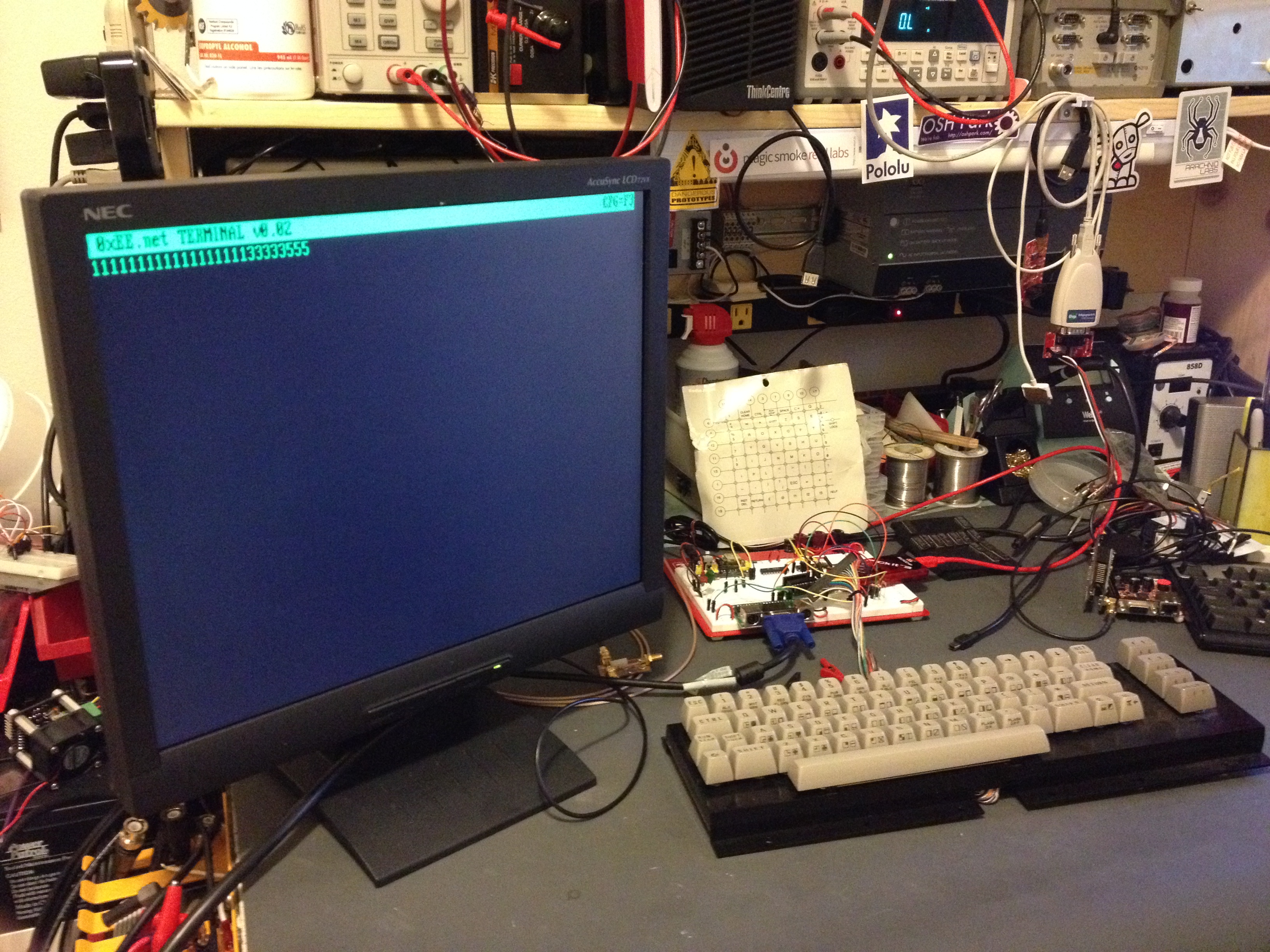
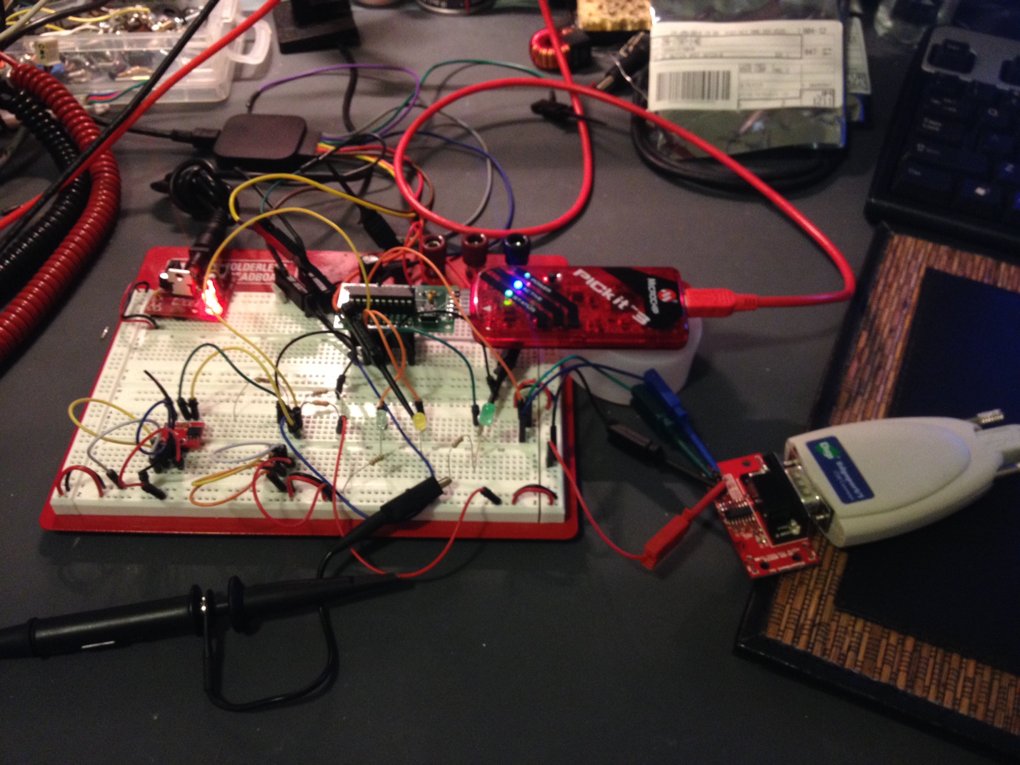
I’m working on a GPS-based WWVB simulator and I’m pretty close to finished. I wanted to share up to the point where I add on the WWVB circuits and have it stripped down to just the PIC development board and GPS module.

This is on a Mikrelektronika PIC Clicker 18F47J53 development board and a QUECTEL L30 “GPS2” Click board (Mikroe’s module boards built for MikroeBus).

The code is below, I’ll leave the rest of the explanation in the video.

NMEA stream from this module


The good stuff..

/*
* File: main.c
* Author: Charles M Douvier
* Contact at: http://iradan.com / 0xEE.net / @chasxmd
* Created on April 4th, 2014
*
* Target Device: PIC Click / 18F47J53
*
* Project: Mikroe.com GPS2 test
* Using a PIC Click Dev board and GPS2 click module I am reading the NMEA
* string and declaring a "lock" by turning on the LED on RA1
*
*
* Version:
* 0.1 First build I could prove I had GPS lock
*
*
*
*/
#ifndef _XTAL_FREQ //blah blah not the right way I don't care
#define _XTAL_FREQ 8000000 //8Mhz FRC internal osc
#define __delay_us(x) _delay((unsigned long)((x)*(_XTAL_FREQ/4000000.0)))
#define __delay_ms(x) _delay((unsigned long)((x)*(_XTAL_FREQ/4000.0)))
#endif

#include
#include
#include
#include

//config bits
#pragma config OSC=INTOSC, WDTEN=OFF, CP0=OFF //Internal OSC, No WDT and No code protect
#pragma config IESO=OFF, FCMEN=OFF
#pragma config XINST = OFF
#pragma config PLLDIV = 1 //Divide by 1
#pragma config STVREN = ON //stack overflow/underflow reset enabled
#pragma config XINST = OFF //Extended instruction set disabled
#pragma config CPUDIV = OSC1 //No CPU system clock divide

#define _XTAL_FREQ 8000000 //defined for delay

char ctxt[120]; //buff NMEA string
volatile unsigned int ping, isrcall, index, reading, new_rx;
int ready, gpgga, gprmc; //gps associated vars
//char *rxdata;
//volatile unsigned int uart_data; // use ‘volatile’ qualifer as this is changed in ISR

/*
* Interrupt Service
*/
void interrupt ISR() {

if (PIR3bits.RC2IF) // see if interrupt caused by incoming data
{
isrcall = 0x01;
char temp;
temp = RCREG2; // read the incoming data
if(temp==’$’ && new_rx==0) //if first char of a GPS string..
{
index = 0; //reset index
reading = 1; //from now on go to else if
}
else if(reading == 1) //in middle of GPS sentence
{
ctxt[index] = temp; //load it up
index++; //increment index
ping = 1; //this is for debugging
if(index > 50) //thats more than enough data
{
index = 0; //reset index
reading = 0; //no longer storing the string
new_rx = 1; //”ding”
}
}
//PIR3bits.RC2IF = 0; // clear interrupt flag
}
//RCSTA2bits.FERR = 0; //Clear errors
//RCSTA2bits.OERR = 0;
}

/*
* Set up my ports
*/
void init_io(void) {
// This code before the TRIS setup is for switching the RX2/TX2 to proper pins for the dev board
INTCONbits.GIE = 0; //no interruptions please
EECON2 = 0x55;
EECON2 = 0xAA;
PPSCONbits.IOLOCK = 0; //turn off PPS write protect

//PPS Info:
//RX2DT2R: EUSART2 Synchronous/Asynchronous Receive (RX2/DT2) to the Corresponding RPn Pin bits
//RP22 000[RX2DT2R4 RX2DT2R3 RX2DT2R2 RX2DT2R1 RX2DT2R0]
//TX2/CK2 6 EUSART2 Asynchronous Transmit/Asynchronous Clock Output
//RP23 000 [RP6R4 RP6R3 RP6R2 RP6R1 RP6R0]
//RD5 RX
//RD6 TX
//sample:
// Assign RX2 To Pin RP0
//MOVLW 0x00 MOVWF RPINR16, BANKED
// Assign TX2 To Pin RP1
//MOVLW 0x06 MOVWF RPOR1, BANKED

RPINR16 = 0x16; //Pin 22 / RD5
RPOR23 = 0x06; //Pin 23 / RD6

EECON2 = 0x55;
EECON2 = 0xAA;
PPSCONbits.IOLOCK = 1; //write protect PPS

LATA = 0x00;

TRISAbits.TRISA0 = 0; //LED1
TRISAbits.TRISA1 = 0; //LED2
TRISAbits.TRISA2 = 0; //POWER ON

TRISBbits.TRISB0 = 0; // HEADER
TRISBbits.TRISB1 = 0; // HEADER
TRISBbits.TRISB2 = 0; // RST
TRISBbits.TRISB3 = 0; // CS
TRISBbits.TRISB4 = 0; // SCK
TRISBbits.TRISB5 = 1; // MISO

LATC = 0x00;

TRISCbits.TRISC0 = 0; // HEADER/DEBUGGING PIN
TRISCbits.TRISC1 = 0; // HEADER/DEBUGGING PIN
TRISCbits.TRISC2 = 0; // HEADER
TRISCbits.TRISC3 = 0; // output
TRISCbits.TRISC6 = 1; // PWM (WAKE UP)
TRISCbits.TRISC7 = 1; // MOSI

TRISDbits.TRISD0 = 1; // SCL
TRISDbits.TRISD1 = 1; // SCA
TRISDbits.TRISD4 = 1; // INT
TRISDbits.TRISD5 = 1; // RX
TRISDbits.TRISD6 = 0; // TX

TRISEbits.TRISE0 = 1; // HEADER
TRISEbits.TRISE1 = 1; // HEADER
TRISEbits.TRISE2 = 1; // HEADER
}
void uart_xmit(unsigned int mydata_byte) {
while(!TXSTA2bits.TRMT); // make sure buffer full bit is high before transmitting
TXREG2 = mydata_byte; // transmit data
}

void serial_init(void)
{
//4800 8N1
// calculate values of SPBRGL and SPBRGH based on the desired baud rate
//- SPEN bit (RCSTA2) must be set (= 1)
//- TRIS bit for RPn2/RX2/DT2 = 1
//- TRIS bit for RPn1/TX2/CK2 = 0 for
//Asynchronous and Synchronous Master modes

PIR3bits.RC2IF=0; // make sure receive interrupt flag is clear

TXSTA2bits.BRGH=1; // select low speed Baud Rate (see baud rate calcs below)
TXSTA2bits.TX9=0; // select 8 data bits
TXSTA2bits.TXEN = 1; // enable transmit
RCSTA2bits.SPEN=1; // serial port is enabled
RCSTA2bits.RX9=0; // select 8 data bits
RCSTA2bits.CREN=1; // receive enabled
SPBRG2=104; // here is calculated value of SPBRGH and SPBRGL
SPBRGH2=0;

__delay_ms(50); // give time for voltage levels on board to settle
uart_xmit(‘R’); // transmit some data for testing
}

int main(void) {
ping = 0;
new_rx = 0;
isrcall = 0;
ready = 0;
gpgga = 0;

init_io();
serial_init();

// set up oscillator control register, using internal OSC at 8MHz.
OSCCONbits.IRCF = 0x07; //set OSCCON IRCF bits to select OSC frequency 8MHz
OSCCONbits.SCS = 0x02; //set the SCS bits to select internal oscillator block
__delay_ms(50); //lets think about life a bit before proceeding..

RCONbits.IPEN = 0;
PIE3bits.RC2IE = 1; //Enable RX2 Interrupt
INTCONbits.PEIE = 1; // Enable peripheral interrupt
INTCONbits.GIE = 1; // enable global interrupt

LATBbits.LATB2 = 0; //GPS Reset
__delay_ms(74);
LATBbits.LATB2 = 1; //pull out of reset

LATAbits.LATA0 = 1; //startup heartbeat LED
__delay_ms(50);
LATAbits.LATA0 = 0;

LATCbits.LATC1 = 1; //proves my ISR RC1 output works
__delay_us(35);
LATCbits.LATC1 = 0;

LATCbits.LATC2 = 1; //proves my New Byte RC2 output works
__delay_us(35);
LATCbits.LATC2 = 0;

ADCON0 = 0b00000000; //don’t need any ADC
ADCON1 = 0b00000000; //speed Vref=AVdd, VssRef=AVss

/* Disable for the time being
* This is TIMER code, untested.
INTCONbits.TMR0IE = 0;
TMR0=0;
T0CONbits.T08BIT = 1;
T0CONbits.T0CS = 0;
T0CONbits.PSA = 0;
T0CONbits.T0PS = 0x04;
INTCONbits.TMR0IF = 0;
T0CONbits.TMR0ON = 1;
*/

while (!PORTCbits.RC6) { //in warmup?
LATAbits.LA2 = 0;
__delay_ms(3);
LATAbits.LA2 = 1; //Turn GPS On
__delay_ms(10);
}

LATAbits.LA2 = 1; //Ensure GPS is On

while (1) {
isrcall = 0;
ping = 0;
gpgga = 0;

if (RCSTA2bits.OERR)
{
RCSTA2bits.CREN=0; //DS39964B-page 347
__delay_us(2);
RCSTA2bits.CREN=1; //Overrun error (can be cleared by clearing bit, CREN)
}

if (new_rx == 1) //got our string…
{
if (strstr(ctxt, “GPGGA”))
{
gpgga = 1;
}
new_rx=0; //finished with GPS string
}
// uart_xmit(‘x’); // this was a test, it works.
if (isrcall) { //testing bits
LATAbits.LATA0 = 1; // $ Detect!
__delay_us(10); //
LATAbits.LATA0 = 0;
}

if (gpgga) {
LATCbits.LATC2 = 1; //GPGGA detect
__delay_us(1); //
LATCbits.LATC2 = 0;
if(ctxt[42] == ‘1’) //this is the 43rd bit but we didn’t drop the $ into the buffer
{ //If “$GPGGA” NMEA message has ‘1’ sign in the 43rd
//position it means that tha GPS receiver has a position fix
//
ready = 1; //This is my “locked” variable for future code
LATAbits.LATA1 = 1; //LOCK LED
LATCbits.LATC1 = 1; //DEBUGGING
__delay_us(1); //
LATCbits.LATC1 = 0;
}
else if (ctxt[42] != ‘1’) //this is the 43rd bit but we didn’t drop the $ into the buffer
{
ready = 0; //
LATAbits.LATA1 = 0; //LOCK LED
}
}
}
}


PIC-based Dumb Terminal

Okay before you start; I know.. I know.. Because I’m shooting for a VT-100-ish emulation my project is technically an “intelligent” terminal but not in a sense that it runs an embedded OS/IP-based, but in the sense that it decodes ANSI ESC codes.. it’s still a freakn’ dumb terminal in my book.

I’m just about finished with the PC board for this and in the photo below is my proof of concept. All the key’s don’t work yet as I don’t have enough IO without some encoding; the keyboard is an old row/column keyboard  I scored off eBay.  Because I want to stick with a smaller PIC I’m going to use 74HC series logic to accomplish this, but I was considering switching to CPLD in a version 2.

My PIC 18F14K22  Dumb Terminal
My PIC 18F14K22 Dumb Terminal

Target Features: Baud change (to terminal) via a config screen on the fly (likely limited it to 1200, 2400, 4800, 9600, 115k). Switching the “retro” color from green, amber, or if you’re boring/have been playing too much telehack, white. Half/Full duplex… no color decoding (or VT220 emulation) but perhaps in the future.

Once my PC board is finished and back from the fab I’ll finish the code and make a proper post… the code isn’t presentable besides at least being decently commented. When will you see my next post on this?….. read on.

I have collaborated with Francesco of GarageTech to create a new site. Francesco had some really good ideas, so I pushed 0xEE.net off to its own site. We’re just ironing out a few details and starting our first articles… look for some good stuff soon! 0xEE.net will be ALL PIC-based… I’m pushing all my PIC based projects over there. I’ll co-post and maintain my blog for all non-PIC based stuff .. but if I’m dropping code and it’s not snippets, I’ll post a generic tidbit and a description here and link in over to 0xEE.

If you’re curious: it’s also not lost on me that you could use RealTerm or PuTTY on your PC… I just think this is nifty if you have the bench space.

Analog Stepper Gauge Friday night fun

Took a while to clear off the bench tonight. I got a little happy with the ORDER button last week through weekend. I’ve filled two more parts storage containers and luckily one of my new packages with another parts storage container from Amazon; I couldn’t find any locally, I hope they’re still making them.

The last thing I got to was this “Gauge Stepper Breakout” I got off The Rengineer (The Renaissance Engineer)’s Tindie store. Adam took this very nice stepper motor, put a gauge needle on it (which I believe he 3D printed, or at least it looks like it) and some nice diodes for voltage protection. What’s great about this board is you can drive it right from your microcontroller. I’m sure I don’t need to tell you how weird that is.. I worry about big LEDs.. but here this stepper was happy as a clam being powered by my PIC. I still might consider at least buffering this if I was to place it in a permanent  circuit.

Adam’s provides links to some Arduino libraries but he was saved me a ton of time and just happened to have some PIC sample code! Not before I had about 75% of a ECCP program completed. (I’ll link some of that code if you’re looking for an example of Enhanced PWM output). Once I had Adam’s code I ported it to the TAUTIC 18F26K22 dev board because I already had one on the breadboard. That was mostly changes in the TMR0 (timer 0) code. The only thing of note is check out my IO comments for wiring. You have to cook up 5V/GND to this board then I drove RC3 –> A1 RC2 — A2, RC1 –> B1 and RC0 –> B2. When I had it flipped around the stepper moved in the opposite direction of how I wanted.

A little video of the code in action:

This code is a little sloppy but I just testing this out and it did the trick:


/*
 * File:   main.c
 * Author: Charles M Douvier  Contact at: http://iradan.com
 * Core Driver Code by Adam F. of http://www.therengineer.com/
 *
 * Created on April 4th, 2014
 *
 * Target Device:
 * TAUTIC PIC 18F26K22 Dev Board
 *
 * Project:
 *
 *
 * Version:
 * 1.0
 *
 */

#ifndef _XTAL_FREQ
#define _XTAL_FREQ 4000000 //4Mhz FRC internal osc
#define __delay_us(x) _delay((unsigned long)((x)*(_XTAL_FREQ/4000000.0)))
#define __delay_ms(x) _delay((unsigned long)((x)*(_XTAL_FREQ/4000.0)))
#endif

#include 
#include 
#include 
#include 

//config bits
#pragma config FOSC=INTIO67, WDTEN=OFF, PWRTEN=OFF, CP0=OFF, CP1=OFF, BOREN=ON
#pragma config STVREN=ON, LVP=OFF, HFOFST=OFF, IESO=OFF, FCMEN=OFF

//WRT=OFF, FOSC=INTOSC, MCLRE=ON

#define _XTAL_FREQ 4000000 //defined for delay
#define MIN_STEPS_LEFT 23
#define MAX_ACCEL_INDEX 6
#define MAX_STEP 945 /* motor can move 945 steps from stop to stop*/

    int     an8_value, an9_value;          //value for a/d
    char    buf[10];            //buff for iota
    long int    fvar;           //long for format math
    long int    tens;           //left of decm
    long int    decm;           //decimal places
    int     tempi;              //to add leadign zeros..
    int     vtxdata;             //volts int for TX
    int     itxdata;

    unsigned short defaultAccelTable[][2] =
{
  {   1750, 3},
  {   1149, 3},
  {  926,   3},
  {  794,   3},
  {  709,   3},
  {  666,   4},
  {  /*629*/450,   4},
};
unsigned int currentStep;
unsigned char currentState;
unsigned char stateMap[] = {0x09, 0x01, 0x07, 0x06, 0x0E, 0x08};
unsigned char serialBuffer[10];
unsigned char serialByteCount;
 static const unsigned char stateCount = 6;

    volatile unsigned int uart_data;    // use 'volatile' qualifer as this is changed in ISR
/*
 *
 */
void interrupt ISR() {

    if (PIR1bits.RCIF)          // see if interrupt caused by incoming data
    {
        uart_data = RCREG;     // read the incoming data
        PIR1bits.RCIF = 0;      // clear interrupt flag
    }

}

void init_io(void) {
    TRISAbits.TRISA0 = 0; // output
    TRISAbits.TRISA1 = 0; // output
    TRISAbits.TRISA2 = 0; // output
    TRISAbits.TRISA3 = 0; // output
    TRISAbits.TRISA4 = 0; // output
    TRISAbits.TRISA5 = 0; // output
    TRISAbits.TRISA6 = 0; // output
    TRISAbits.TRISA7 = 0; // output

    ANSELA = 0x00; // all port A pins are digital I/O

    LATAbits.LATA0 = 0;
    PORTAbits.RA0 = 0;

    TRISBbits.TRISB1 = 0;   //P1C output
    TRISBbits.TRISB2 = 0;  // P1B output
    TRISBbits.TRISB3 = 1;  // AN9    speed control 0-5V
    TRISBbits.TRISB4 = 0;  // P1D output
    TRISBbits.TRISB5 = 1; // RB5 = nc
    TRISBbits.TRISB6 = 0; // RB6 = nc
    TRISBbits.TRISB7 = 0; // RB7 = nc

    ANSELB = 0b00001000;     //RB3, AN9

    TRISCbits.TRISC0 = 0; // output to B2 .. reversed to stoke the right direction
    TRISCbits.TRISC1 = 0; // output to B1
    TRISCbits.TRISC2 = 0; // output to A2
    TRISCbits.TRISC3 = 0; // output to A1
    TRISCbits.TRISC4 = 0; // output
    TRISCbits.TRISC5 = 0; // output
    TRISCbits.TRISC6 = 0; // output
    TRISCbits.TRISC7 = 0; // output
    ANSELC = 0x00; // all port B pins are digital I/O
}

void uart_xmit(unsigned int mydata_byte) {

    while(!TXSTA1bits.TRMT);    // make sure buffer full bit is high before transmitting
    TXREG = mydata_byte;       // transmit data
}

void serial_init(void)
{
    //9600 8N1
    // calculate values of SPBRGL and SPBRGH based on the desired baud rate
    //
    // For 8 bit Async mode with BRGH=0: Desired Baud rate = Fosc/64([SPBRGH:SPBRGL]+1)
    // For 8 bit Async mode with BRGH=1: Desired Baud rate = Fosc/16([SPBRGH:SPBRGL]+1)

    TXSTA1bits.BRGH=1;       // select low speed Baud Rate (see baud rate calcs below)
    TXSTA1bits.TX9=0;        // select 8 data bits
    TXSTA1bits.TXEN = 1;     // enable transmit

    RCSTA1bits.SPEN=1;       // serial port is enabled
    RCSTA1bits.RX9=0;        // select 8 data bits
    RCSTA1bits.CREN=1;       // receive enabled

    SPBRG1=25;  // here is calculated value of SPBRGH and SPBRGL
    SPBRGH1=0;

    PIR1bits.RCIF=0;        // make sure receive interrupt flag is clear
    PIE1bits.RCIE=1;        // enable UART Receive interrupt
    INTCONbits.PEIE = 1;    // Enable peripheral interrupt
    INTCONbits.GIE = 1;     // enable global interrupt

         __delay_ms(50);        // give time for voltage levels on board to settle

    uart_xmit('R');         // transmit some data
}

// All this motor and timer code is from Adam with very minor changes to fit the processor

void t0Delay(unsigned int usec)
{
    unsigned int t0ticks; //16 microsecond timer0 ticks
    unsigned char t0Preload;
    if(usec<16)
    {
        t0ticks=1;
    }
    else
    {
        t0ticks = usec/16;
    }
    t0Preload = 0xFF - t0ticks;
    INTCONbits.TMR0IF=0; //clear the flag
    TMR0 = t0Preload;
    while(INTCONbits.TMR0IF==0)
    {
        ;
    }
}

void zeroMotor()
{
    unsigned int i;
    for (i=0; i < MAX_STEP; i++)
    {
        LATC=stateMap[currentState];
        currentState = (currentState + 5) % stateCount;
        t0Delay(1900);  //2200 in datasheet
    }
    //now the motor is zeroed, reset our state variables.
    currentStep = 0;
    currentState = 0;
    LATC=0; //turn off coils
}

void moveMotor(unsigned int targetStep)
{
    unsigned int dir;
    unsigned int curDelay;
    unsigned char speedIndex=0;
    unsigned char stepsAtThisSpeed=0;
    unsigned int stepsLeft;
    if(currentStep<targetStep)     {         dir = 1;         stepsLeft = targetStep-currentStep;     }     else     {         dir = -1;         stepsLeft = currentStep - targetStep;     }     while(stepsLeft>0)
    {
        if(stepsLeft<=MIN_STEPS_LEFT)         {             //decellerating             if(stepsAtThisSpeed==0)             {                 if(speedIndex>0)
                    speedIndex--;
                curDelay=defaultAccelTable[speedIndex][0];
                stepsAtThisSpeed=defaultAccelTable[speedIndex][1];
            }
        }
        else
        {

            //accellerating or steady state
            if(stepsAtThisSpeed==0)
            {
                if(speedIndex<MAX_ACCEL_INDEX)                 {                     speedIndex++;                     curDelay=defaultAccelTable[speedIndex][0];                     stepsAtThisSpeed=defaultAccelTable[speedIndex][1];                 }                 //else we're at steady state - do nothing.             }         }         //write step         LATC=stateMap[currentState];         if(dir==1)         {             currentState = (currentState + 1) % stateCount;         }         else         {             currentState = (currentState + 5) % stateCount;         }         t0Delay(curDelay);         if(stepsAtThisSpeed>0)
        {
            stepsAtThisSpeed--;
        }
        stepsLeft--;
        currentStep+=dir;
    }
}

int main(void) {

    init_io();
    serial_init();

    // set up oscillator control register, using internal OSC at 4MHz.
    OSCCONbits.IRCF = 0x05; //set OSCCON IRCF bits to select OSC frequency 4MHz
    OSCCONbits.SCS = 0x02; //set the SCS bits to select internal oscillator block

    ADCON0 = 0b00100101;                            //select AN9 and enable
    ADCON1 = 0b00000000;                  //speed Vref=AVdd, VssRef=AVss
    ADCON2 = 0b00111011;                //ledft justified, 20RAD, FRC

    INTCONbits.TMR0IE = 0;

    TMR0=0;

    T0CONbits.T08BIT = 1;
    T0CONbits.T0CS = 0;
    T0CONbits.PSA = 0;
    T0CONbits.T0PS = 0x04;
    INTCONbits.TMR0IF = 0;

        T0CONbits.TMR0ON = 1;

    __delay_us(5);

    currentStep = 0;
    currentState = 0;

    zeroMotor();         
    __delay_ms(149);        //this could be less messy
    __delay_ms(149);
    __delay_ms(149);
    __delay_ms(149);
    __delay_ms(149);
    __delay_ms(149);
    moveMotor(20);
    __delay_ms(149);
    __delay_ms(149);
    __delay_ms(149);
    __delay_ms(149);
    __delay_ms(149);
    __delay_ms(149);

    moveMotor(940);
    moveMotor(5);

    while (1) {

        //PORTAbits.RA0 = 1;      //heart beat
        //__delay_ms(50);
        //PORTAbits.RA0 = 0;
        //__delay_ms(50);

        ADCON0 = 0b00100101;    //select AN9 and enable
        __delay_us(5);
        GO = 1;
        while (GO) continue;    //wait for conversion
        an9_value = ADRESH;     //AN9 value

        fvar = an9_value;
        fvar = fvar * 10749;    //calibration.. change to meet your needs
        fvar = fvar / 256;
        tens = fvar / 100;
        //tens = tens % 10;
        decm = fvar % 100;
        vtxdata = fvar / 20;
        uart_xmit(vtxdata);    // -->RS232

        moveMotor(vtxdata);
        //moveMotor(5); //from sample code
    }
    return (EXIT_SUCCESS);
}

Some ECCP ( Enchanced PWM ) code written for the PIC 18F26K22 code I wrote following the screen shot of the output:

Deadband on Enhance PWM mode output on PIC

void pwm_init(){

//    CCPR1L = 0x120;
    CCPR1Lbits.CCPR1L = 0xFE;
    PR2 = 0xFE;
    CCPTMRS0bits.C1TSEL = 0;     //CCP TMR2 Selection
    CCP1CONbits.P1M = 0x02;     //half bridge
    CCP1CONbits.DC1B = 0x00;
    PWM1CONbits.P1RSEN = 0;
    PWM1CONbits.P1DC = 0x1F;    //dead band delay
    ECCP1ASbits.CCP1AS = 0x00;
    ECCP1ASbits.CCP1ASE = 0;    //Auto-shutdown off
    CCP1CONbits.CCP1M = 0x0C;
    PSTR1CONbits.STR1A = 1;
    PSTR1CONbits.STR1B = 1;

    T2CONbits.T2CKPS = 1;
    T2CONbits.TMR2ON = 1;

}

//.. now dump something smaller than 127 into CCPR1Lbits.CCPR1L
//to set the pulse width

PIC 18F26K22 PWM+A/D with MOSFET, the start of an eScooter?

I’m considering building an electric scooter; considering it probably putting it lightly.. I have almost everything I need for it.  Interested? Why type so much when you can just watch my proof of concept!

If you’re following along and want to use the same hardware (warning totally untested… ):
Controller found on the TAUTC Tindie Store
Search on eBay for “24VDC scooter motor” ..
..and pick up a MOSFET that’ll pull off a couple 20 amps and saturates at or below 5VDC.
…what am I talking about? Try google or read this.

To the important stuff, the code:


/* 
 * File:   main.c
 * Author: Charles M Douvier
 * Contact at: http://iradan.com
 *
 * Created on March 27, 2014, 4:12 PM
 *
 * Target Device:
 * 18F26K22 on TAUTIC Dev Board
 *
 * Project:
 * Electric Scooter
 *.. a real hack job, comment, delete garbage, etc.
 *
 * Version:
 * 0.1
 *
 */
#ifndef _XTAL_FREQ
#define _XTAL_FREQ 4000000 //4Mhz FRC internal osc
#define __delay_us(x) _delay((unsigned long)((x)*(_XTAL_FREQ/4000000.0)))
#define __delay_ms(x) _delay((unsigned long)((x)*(_XTAL_FREQ/4000.0)))
#endif

#include 
#include 
#include 
#include 

//config bits
#pragma config FOSC=INTIO67, WDTEN=OFF, PWRTEN=OFF, CP0=OFF, CP1=OFF, BOREN=ON
#pragma config STVREN=ON, LVP=OFF, HFOFST=OFF, IESO=OFF, FCMEN=OFF

//WRT=OFF, FOSC=INTOSC, MCLRE=ON

#define _XTAL_FREQ 4000000 //defined for delay

//clean up on isle 2.. 

    int     an9_value;          //value for a/d
    char    buf[10];            //buff for iota
    long int    fvar;           //long for format math
    long int    tens;           //left of decm
    long int    decm;           //decimal places
    int     tempi;              //to add leadign zeros..
    int     vtxdata;             //volts int for TX
    int     itxdata;

    volatile unsigned int uart_data;    // use 'volatile' qualifer as this is changed in ISR
/*
 * 
 */
void interrupt ISR() {

    if (PIR1bits.RCIF)          // see if interrupt caused by incoming data
    {
        uart_data = RCREG;     // read the incoming data
        PIR1bits.RCIF = 0;      // clear interrupt flag
    }

}

void init_io(void) {
    TRISAbits.TRISA0 = 0; // output
    TRISAbits.TRISA1 = 0; // output
    TRISAbits.TRISA2 = 0; // output
    TRISAbits.TRISA3 = 0; // output
    TRISAbits.TRISA4 = 0; // output
    TRISAbits.TRISA5 = 0; // output
    TRISAbits.TRISA6 = 0; // output
    TRISAbits.TRISA7 = 0; // output

    ANSELA = 0x00; // all port A pins are digital I/O

    TRISBbits.TRISB3 = 1; // AN9
    TRISBbits.TRISB4 = 0; // RB4 = nc
    TRISBbits.TRISB5 = 1; // RB5 = nc
    TRISBbits.TRISB6 = 0; // RB6 = nc
    TRISBbits.TRISB7 = 0; // RB7 = nc

    ANSELB = 0b00001000;     //RB3, AN9

    TRISCbits.TRISC0 = 0; // output
    TRISCbits.TRISC1 = 0; // output
    TRISCbits.TRISC2 = 0; // output
    TRISCbits.TRISC3 = 0; // output
    TRISCbits.TRISC4 = 0; // output
    TRISCbits.TRISC5 = 0; // output
    TRISCbits.TRISC6 = 1; // input
    TRISCbits.TRISC7 = 1; // input
    ANSELC = 0x00; // all port C pins are digital I/O
}

void pwm_init(){

//         PSTR1CONbits.STR1A
//hackhackhackhack... TODO

//    CCPR1L = 0x120;
    CCPR1Lbits.CCPR1L = 0xFE;
    PR2 = 0xFE;
    CCPTMRS0bits.C1TSEL = 0;     //CCP TMR2 Selection
    CCP1CONbits.P1M = 0x00;
    CCP1CONbits.DC1B = 0x00;
    PWM1CONbits.P1RSEN = 0;
    T2CONbits.T2CKPS = 1;  //1:2 Prescale
    T2CONbits.TMR2ON = 1;  //timer 2 go

    CCP1CON = 0x0C;       //PWM (CCP)1 ON

}

void uart_xmit(unsigned int mydata_byte) {

    while(!TXSTA1bits.TRMT);    // make sure buffer full bit is high before transmitting
    TXREG = mydata_byte;       // transmit data
}

void serial_init(void)
{
    //9600 8N1
    // calculate values of SPBRGL and SPBRGH based on the desired baud rate
    //
    // For 8 bit Async mode with BRGH=0: Desired Baud rate = Fosc/64([SPBRGH:SPBRGL]+1)
    // For 8 bit Async mode with BRGH=1: Desired Baud rate = Fosc/16([SPBRGH:SPBRGL]+1)

    TXSTA1bits.BRGH=1;       // select low speed Baud Rate (see baud rate calcs below)
    TXSTA1bits.TX9=0;        // select 8 data bits
    TXSTA1bits.TXEN = 1;     // enable transmit

    RCSTA1bits.SPEN=1;       // serial port is enabled
    RCSTA1bits.RX9=0;        // select 8 data bits
    RCSTA1bits.CREN=1;       // receive enabled

    SPBRG1=25;  // here is calculated value of SPBRGH and SPBRGL
    SPBRGH1=0;

    PIR1bits.RCIF=0;        // make sure receive interrupt flag is clear
    PIE1bits.RCIE=1;        // enable UART Receive interrupt
    INTCONbits.PEIE = 1;    // Enable peripheral interrupt
    INTCONbits.GIE = 1;     // enable global interrupt

         __delay_ms(50);        // give time for voltage levels on board to settle

    uart_xmit('R');         // transmit some data "restart" notification
}

int main(void) {

    init_io();
    serial_init();
    LATCbits.LATC2 = 0;
    pwm_init();

    // set up oscillator control register, using internal OSC at 4MHz.
    OSCCONbits.IRCF = 0x05; //set OSCCON IRCF bits to select OSC frequency 4MHz
    OSCCONbits.SCS = 0x02; //set the SCS bits to select internal oscillator block

    ADCON0 = 0b00100101;                            //select AN9 and enable
    ADCON1 = 0b00000000;                  //speed Vref=AVdd, VssRef=AVss
    ADCON2 = 0b00111011;                //ledft justified, 20RAD, FRC
    __delay_us(5);

//loop

    while (1) {

        PORTAbits.RA0 = 1; //blinky i'm alive.
        __delay_ms(140);
        PORTAbits.RA0 = 0;
        __delay_ms(140);

            GO = 1;
    while (GO) continue;              //wait for conversion
    an9_value = ADRESH;               //AN9 value

        fvar = an9_value; //this is hacked off another project but works
        fvar = fvar * 10749;        //calibration
        fvar = fvar / 256;
        tens = fvar / 100;
        //tens = tens % 10;
        decm = fvar % 100;
        vtxdata = fvar / 43; //because I'm lazy... I'll change this later.
        uart_xmit(vtxdata);
        CCPR1Lbits.CCPR1L = vtxdata;

    }
    return (EXIT_SUCCESS);
}

A tiny Si4707 WX Radio Project Update

I pulled out the weather radio project today to see what I could get done in a few hours. I was pretty close on finishing off the hardware but I fell a little short right at the end. I found I had forgotten to buy something to convert the regulated 5V to 3.3V for the radio (and PIC since they’re tied together on I2C). I ran into a few issues I totally spaced:1.  The Si4707 requires a reset after power up .. it ignores I2C if you don’t.

2. Pull-ups.. duh, not only on I2C which I had, but don’t forget the Si4707 reset (oops).

I ended up buying a couple random Digikey parts at the ham radio convention and guess what? 10@ MCP1802T-3002I/OT (300mA 3.0V LDO) ..they are SOT23-5 and I had JUST gotten 10 break-out boards in the mail so I ended up having a 5V3.3V converter (close enough anyways, as the PIC and Si4707 work down to 2.7V).. soldered it up but I didn’t have time to pop it in. I used the Weller but I think I’m going to solder another one with the new hot air gun I got this week. I ordered one of those cheap 858D rework stations; I don’t plan on using it too much so hopefully it’ll do the trick. I also got a bunch of SMD protoboards.. so I get to practice reflow this week.

Tomorrow I should be able to finish up the radio and then it’s all software.

Si4707 WX Radio Build - 11MAR14

The photo isn’t the most exciting workbench shot but you can see that 858D in the back corner. The WX radio is the black box right up close to the left.

An evening of measuring inductance

I was inspired by Alan Wolke’s ( @W2AEW ) video on measuring capacitors and inductors with an oscilloscope. I tried it out and it works pretty reasonably; yeah why wouldn’t it? Anyhow, if you can do it on an oscilloscope it can be done by a microcontroller right?  I have been trying to keep myself from buying this $220 eBay LCR meter on eBay.. it looks nice enough (model: MCH2811C). I needed to make this a project or I was going to pull the trigger on some Chinese garbage!

I went with simple and cheap, I don’t know how well it’ll work out yet but I bread-boarded a proof of concept design. It tested okay after some modification. The first road bump was I had found the PIC output pins had unacceptable rise time compared to 74HC14. The first change was using the PIC output to drive the 74HC14 HEX inverter to get the quick rise time needed.  I’m throwing a fast edge at the tank circuit that includes an “unknown” inductor and then I do my measurement, just as Alan used his homebrew TDR circuit. I went really low tech on my measurement circuit, I may change this. I used an LM339 comparator and a trimmer as a voltage divider. The first couple waves in the tank “ring” trigger the comparator and I measure the frequency by figuring out the time between the positive pulses by timer. Pretty simple no? It works fine as it turns out. I will have to get a better capacitor and ensure I measure it very accurately to do my math in the PIC and get a reasonable result.

Instead of the usual photos I made another YouTube video. It wasn’t a great one, one take, no editing.. it’s gets my point across (kind of).

My project proof of concept for the PIC L-meter. With the addition of a known inductor and a rotary switch and a little more code you can turn this into a PIC LC-meter in no time.


Project Update: Spunk The Annoying Robot

The last robot I built was a Roomba Sumo Robot (Talos) for a small competition with co-workers. While collecting parts for this little eBay robot platform I got for somewhere in the neighborhood of 15$USD, I grabbed my Pololu motor controller and remember that I wrote that whole Sumo robot in ASM; that was a lot of code between two PICs.

The little robot I’m building now has very few specifications. It’s goal in life is to follow you around, but not too close. It should back away when needed and basically run around, pausing for a while in its search for someone to follow around. My wife named it Spunk because she’s certain to be the one it annoys most.

I’ve built the project as seen in the photo and written all primary code.. ordered a lot of battery management parts to see what I like the best. Determined I can’t get the robot to “find” people with the sensors I have, so I ordered more… so this little guy is half-done. I’ll shelve him until more parts arrive. I really only grabbed it down as it was 4 projects deep in the to-do list because I haven’t kept up with pre-ordering parts, or worse.. ordered the wrong things. I’m still on the hunt for a better display for the WX radio, ordered items for my RS-485 project, etc. etc..

The heart of Spunk is a PIC 18F14K22 on a TAUTIC 20 pin development board. Maybe Jayson ( @TAUTIC ) needs to pay me for all this advertising? 😉 jk.. I just bought a couple of the boards because they fit my type of prototyping perfectly. This was my last one… time to make an order over at @tindie for some more.

Spunk getting probed.

For now, no code. I’ll post the old ASM code for the Pololu motor controller and the C code as well once it get it properly commented and make sure it at least mostly works. Once I do some real roving tests I’ll throw it on YouTube (and maybe the first tests of Talos as well)… TBC for now.

Checkout: @tymkrs MIDI In Me + PIC18F14K22

I don’t want anyone thinking they’re going to see a bunch of music related items on the blog because I’m really no good at such things. My brother on the other hand is very talented and we recently decided he needed some more MIDI toys. A lot of his music is already created with the help of MIDI.

MIDI is “Musical Instrument Digital Interface“; a standard that defines hardware and protocol. If you want more information on it such as specifications Google is your friend.

My brother had some information on the specification but not really anything that helped me much. I did a lot of reading on the specifications on the MIDI Manufacturers Association webpage and then countless other sites describing the protocol in length. It even looks like there is a tutorial on the Arduino site, although I didn’t look at it because I don’t use them. Again, I’m not going to go into the protocol anymore than I discussed the specification. I’ll let you do that leg work. However, the *really* short version is there are a couple key commands followed (usually) by some extra bytes (generally 1 or 2). All the data is transmitted like normal 8N1 serial data at 31.25kbaud. Lucky for me 31.5k has a nice PIC SPBRG division value for low error rate (at 4MHz).

Hardware Interface: I decided I wasn’t going to build the 5mA loop interface and I remembered the Toymakers ( @tymkrs ) had a nice little interface board already built. One trip on over to their Tinde Store and I had it a few days later.

It’s a small kit, it came well packed, and it fit the bill just fine. I have nothing but praise this little kit with only one tiny little nit-picky mention. I wish they included a URL of the location of the instructions for building the kit. They had a couple resistors and I needed to know what was R1, R2, etc.. it was easy to find, a return trip to Tindie linked instructions, a construction video! and a lot of information on their website. So I know I’m picky.. If they wanted to make a 9.7 a 10.. that’d be it 😉

The Toymakers Midi In Me Kit.

After everything was plugged in, code was loaded on the PIC, a MIDI device plugged in.. etc.. I checked out the MIDI kit to see response and how noisy it might be… no complaints here.. it looked good…

MIDI In signal edge TEK0000

The Firmware: It’s just “sample” code. I haven’t written any real output yet because my brother is in charge of the “analog” bits which really means he is going to figure out what he wants in block diagrams and I will have to figure out how to make it happen in circuit. Right now I’m reading the MIDI signal in on UART by interrupt… and checking for my command signal. (I’m using a Control Change because of my MIDI device… you will most likely want to change this). The control change value is 0xB1 in my case, then… my device (Knob #1) which is 0x11 … and finally it gives me a value (knob position 0x00 to 0x7F). I’m taking that position value and transmitting it out the UART to my PC…


The output dropped onto my PC. Note: RealTerm allows me to enter in 31250 baud.. 8N1
MIDI on the LA
MIDI on the LA


I used the TAUTIC 20 pin dev board (any groaning of “AGAIN??”??) … but a change-up! 🙂 I used a PIC 18F14K22 … because I felt like getting crazy 😉 and the 18 series is optimized for C so I will probably go back to the 18F series … I think the last time I used one was my ESR meter?  A few changes switching to the 18 series.. but nothing huge. Just getting used to slightly different registers.  Last warnings about the code; It’s simple… it’s just checking to see if your interface it working… (or if you’re sending MIDI and you don’t have a scope or LA). It has a lot of clutter because I was using it for some other non-MIDI related testing but it’s easy to spot and delete if you need to copy it as a starting point for whatever you’re working on. (Do share!)

/* 
 * File:   main.c
 * Author: Charles M Douvier
 * Contact at: http://iradan.com
 *
 * Created on February 8, 2014, 11:39 AM
 *
 * Target Device:
 * 18F14K22 on Tautic 20 pin dev board
 *
 * Project: MIDI Slave
 *
 *
 * Version:
 * 0.1  Configuration, 31.25Kbaud TX&RX
 * 0.2  Grab MIDI byte from 31.25K MIDI and turn around and TX the value of the
 *      MIDI command. <CMD: Control Change><Device><Value>
 *      <B1><11><value> //my example
 *
 */
#ifndef _XTAL_FREQ
#define _XTAL_FREQ 4000000 //4Mhz FRC internal osc
#define __delay_us(x) _delay((unsigned long)((x)*(_XTAL_FREQ/4000000.0)))
#define __delay_ms(x) _delay((unsigned long)((x)*(_XTAL_FREQ/4000.0)))
#endif

#include <xc.h>
#include <stdio.h>
#include <stdlib.h>
#include <string.h>

//config bits
#pragma config FOSC=IRC, WDTEN=OFF, PWRTEN=OFF, MCLRE=ON, CP0=OFF, CP1=OFF, BOREN=ON
#pragma config STVREN=ON, LVP=OFF, HFOFST=OFF, IESO=OFF, FCMEN=OFF

#define _XTAL_FREQ 4000000 //defined for delay

/*
 * Variables
 */

    long int    decm;           //long temp
    int     tempi;              //temp
    int     i, ilevel;                  //temp
    int     itxdata;            //int RS232 tx data
    char    buf[10];            //buff for iota
    volatile unsigned int uart_data;    // use 'volatile' qualifer as this is changed in ISR

/*
 *  Functions
 */

    void interrupt ISR() {

    if (PIR1bits.RCIF)          // see if interrupt caused by incoming data
    {
        uart_data = RCREG;     // read the incoming data
        PIR1bits.RCIF = 0;      // clear interrupt flag
                                //
    }

}

void uart_xmit(unsigned int mydata_byte) {

    while(!TXSTAbits.TRMT);    // make sure buffer full bit is high before transmitting
    TXREG = mydata_byte;       // transmit data
}

void serial_init(void)
{

    // calculate values of SPBRGL and SPBRGH based on the desired baud rate
    //
    // For 8 bit Async mode with BRGH=0: Desired Baud rate = Fosc/64([SPBRGH:SPBRGL]+1)
    // For 8 bit Async mode with BRGH=1: Desired Baud rate = Fosc/16([SPBRGH:SPBRGL]+1)

    TXSTAbits.BRGH=1;       // select low speed Baud Rate (see baud rate calcs below)
    TXSTAbits.TX9=0;        // select 8 data bits
    TXSTAbits.TXEN = 1;     // enable transmit

    RCSTAbits.SPEN=1;       // serial port is enabled
    RCSTAbits.RX9=0;        // select 8 data bits
    RCSTAbits.CREN=1;       // receive enabled

    //BRGH=1        31.25KHz
    //SPBRG=7

    SPBRG=7;               //

    PIR1bits.RCIF=0;        // make sure receive interrupt flag is clear
    PIE1bits.RCIE=1;        // enable UART Receive interrupt
    INTCONbits.PEIE = 1;    // Enable peripheral interrupt
    INTCONbits.GIE = 1;     // enable global interrupt

         __delay_ms(50);        // give time for voltage levels on board to settle

    //  uart_xmit('S');         // transmit a character example

}

void init_io(void) {
    TRISAbits.TRISA0 = 0; // output
    TRISAbits.TRISA1 = 0; // output
    TRISAbits.TRISA2 = 0; // output
    TRISAbits.TRISA4 = 0; // output
    TRISAbits.TRISA5 = 0; // output

    ANSEL = 0x00;         // no A/D
    ANSELH = 0x00;

    TRISBbits.TRISB4 = 0; // RB4 = nc
    TRISBbits.TRISB5 = 1; // RB5 = nc
    TRISBbits.TRISB6 = 0; // RB6 = nc
    TRISBbits.TRISB7 = 0; // RB7 = nc

    TRISCbits.TRISC0 = 0; // output
    TRISCbits.TRISC1 = 0; // output
    TRISCbits.TRISC2 = 0; // output
    TRISCbits.TRISC3 = 0; // output
    TRISCbits.TRISC4 = 0; // output
    TRISCbits.TRISC5 = 0; // output
    TRISCbits.TRISC6 = 1; // input
    TRISCbits.TRISC7 = 1; // input

}

void set_cmd11(void)
{
    //set an AD output
                while(uart_data==0x11)
            {
                i++; //wait for next char
            }
            ilevel = uart_data;         //finally the value
            uart_xmit(ilevel);
}

void check0xb1(void)
{
    if (uart_data == 0xB1)
    {
            while(uart_data==0xB1)
            {
                i++; //wait for next char
            }
            if ( uart_data == 0x11)     //and the knob 1 is "device 11"... 
               set_cmd11();
    }
}

int main(void) {

    init_io();

    // set up oscillator control register, using internal OSC at 4MHz.
    OSCCONbits.IRCF = 0x05; //set OSCCON IRCF bits to select OSC frequency 4MHz
    OSCCONbits.SCS = 0x02; //set the SCS bits to select internal oscillator block

    serial_init();

    decm=30;            //testing

    ltoa(buf,decm,10);  //long conversion to buffer
    tempi=strlen(buf);  //uh, adding leading zeros..
    uart_xmit('+');
    uart_xmit(itxdata);
    uart_xmit('.');
    LATAbits.LATA0=0;

    while (1) {

        i++;

        while (uart_data)
        {
            check0xb1();    //my midi device is sending a Control Change 0xB1
            uart_data=0;
        }

    }
    return (EXIT_SUCCESS);
}


Project: Si4707 Weather Radio

I purchased a Silicon Labs Si4707 weather band radio break out board (BOB) from Sparkfun a couple of months ago and finally did something with it. The Si4707 has a SAME ( Specific Area Message Encoding ) processor that allows alerting for only for a certain kinds of warnings. The weather band radio board receives from 162.40MHz to 162.55MHz; Its outputs is a 1/8″ jack with enough output to power a small speaker with low volume or earphones at a comfortable level of listening.

LCD Display of Si4707 Weather Band Radio Project

For my project I used MPLABX 2.0 with the XC8 C compiler. I decide to post this project before I was done programming because I’m about to customize this project for what I want. I thought it was a good time to make it available if a reader was interested in customizing the project without all the work of tearing apart what I had done. The code has all the right nuts and bolts and at most of the hard work done for you. All a person needs to do is a little(?) configuration to make the project meet your needs. You might consider going in another direction; volume up/down (programmable feauture!), tune up/down, and of course working with the SAME information, who knows?

Right now on the bench the PIC powers up, resets and powers up the radio, then tunes the radio via I2C to 162.55MHz. It finishes up by reading back the status and then dumps the Tuned Frequency and RSSI ( Received Signal Strength Indicator ) on to the LCD… then off to infinite loop land. In the next few days I plan on having my seven buttons for “quick tune” to the common frequencies (.40, 425, .45, etc..) and one additional monitor/standby switch. My radio will normally be silent and once it receives a weather alert it will un-mute the speaker and alert the LCD. The Standby/Monitor button will reset my alert.

I’ll throw my finished code up on github and you can download my version in a week or so [I’ll edit this and drop a link in when I’ve actually done this].

Another note of interest: the output of the audio amplifier is kind of weak. I recommend building another amplifier stage if you want the thing to wake you up in a weather emergency.

The attached code this is really rough around the edges.. I lot of hacking went into this and all of the unused functions are totally untested.

The Si4707 WX RX:

Okay, so $30.. not a bad price. And in the end I’m happy with the performance.

HOWEVER! The items I don’t like about it…

1. Sparkfun’s BOB threw pull up resistors on it.. that is annoying. I realize you can cut them out but .. how about some 2mm jumpers or something? I got burnt by them trying to get the I2C working. (RTFM!) 🙂 I noticed lot of people seem to have issues with them being poorly sized according to the feedback I’ve read.

2. Wow it this thing pokey. I was a little confused by the application note for the product to determine worst case tune time, etc… basically I just ended up putting in 1000ms because 300ms was hit and miss for me. If I read it correctly worse case tune time for the AM radio version of the chip is 28 seconds!?

3. I2C! Well it worked fine but I suspect the board is a little noisy? with about 2 inches of wire leads I got enough ringing when the BOB wasn’t loaded by the logic analyzer for comm to fold. I ended up have to enable slew.  I also slowed the unit down to 25KHz from 100KHz because I have to wait for it anyways. It’ll probably work fine at 100KHz with slew on.

Top view of Si4707 Weather Band Radio Project. The power supply sits on the back of the LCD/keypad support board and the weather band sits sandwiched between the TAUTIC dev board and daughter-protoboard. The speaker was just thrown in there for quick testing.

The circuit in general:

I haven’t included a schematic nor do I have any plans to. The photos show you I really am not using any support components besides LCD 10k pot you normally put on an LCD. I would have had pull up resistors but they were not required because of the BOB having them pre-installed.  You should be able to re-create the circuit just by looking at my TRISx/LATx initialization in the code. I commented it my version of adequate-enough… If you’re stumped, just ask!

5.0V input to run the LCD backlight and LCD main power (a standard 2 line 44780 compatible). The five volts also feeds the switching power supply to supply the PIC and 4707 with 3.3V power. I mistakenly thought the 4707 ran on 3.3V because I had been using an I2C product that was 3.3V only then had done a little switching around, oops… no harm, just a waste of the regulator. The 4707 runs 2.7-5.5V. My push button switches are designed to run in a 2×4 matrix. See the //notes in the code. Finally my PIC. I’m using (again!) the Microchip PIC 16F1509 microcontroller with a Tautic 20 pin development board and it’s daughter-board for a little prototyping space. I could maybe stretch this 20 PIN MCU a little more but I probably should have picked a slightly larger PIC for the IO. It’s enough for me though.

Side view. Note the whole project was just slapped on top of a piece of old PCB.. It's not even FR4.. just some old stuff. I made some "mounts" out of small copper strap and soldered the protoboard to the bare copper clad board.
Side view. Note the whole project was just slapped on top of a piece of old PCB.. It’s not even FR4.. just some old stuff. I made some “mounts” out of small copper strap and soldered the protoboard to the bare copper clad board.

So my final thoughts are I still have a lot of work and a lot of clean up work on this project. My temp mounting doesn’t have me totally won over. I also don’t like my “keypad” … I might by a pre-build “shield” and adapt it or maybe design my own PCB. I haven’t even hooked up the buttons because I haven’t decided if I’m happy-enough if the hardware.

The code:


/*
 * File:   newmain.c
 * Author: Charles M Douvier
 * Contact at: http://iradan.com
 *
 * Created on January 26, 2014, 12:00 PM
 *
 * Target Device:
 * 16F1509 on Tautic 20 pin dev board
 *
 * Project:
 *  I2C Testing with the TCN75A
 *
 * Version:
 * 0.1  Start Bit, and Control Byte ... check
 * 0.2  /ACK NAK and Stop ... check!
 * 0.3  works+232
 *
 */
#ifndef _XTAL_FREQ
#define _XTAL_FREQ 4000000 //4Mhz FRC internal osc
#define __delay_us(x) _delay((unsigned long)((x)*(_XTAL_FREQ/4000000.0)))
#define __delay_ms(x) _delay((unsigned long)((x)*(_XTAL_FREQ/4000.0)))
#endif

#include 
#include 
#include 
#include 

//config bits
#pragma config FOSC=INTOSC, WDTE=OFF, PWRTE=ON, MCLRE=ON, CP=OFF, BOREN=OFF, CLKOUTEN=OFF, FCMEN=OFF
#pragma config WRT=OFF, STVREN=OFF, LVP=OFF


#define _XTAL_FREQ 4000000 //defined for delay
#define device_address  0b1001000       // unused for now

    unsigned int ACK_bit;
    int i, x;   //garbage flags
    long int tempi, tempn, tempx, tempy, temp10, temp25;
    unsigned char byte, tempbyte1, tempbyte2;
    unsigned char StatusByte;
    unsigned char RESP1Byte, RESP2Byte, RESP3Byte, RESP4Byte, RESP5Byte;
    unsigned char RESP6Byte, RESP7Byte, RESP8Byte, RESP9Byte, RESP10Byte;
    unsigned char RESP11Byte, RESP12Byte, RESP13Byte, RESP14Byte;
    char buf[10];

void init_io(void) {

    ANSELA = 0x00; // all port A pins are digital I/O
    ANSELB = 0x00; // all port A pins are digital I/O
    ANSELC = 0x00; // all port B pins are digital I/O

    TRISAbits.TRISA0 = 0; // keypad strobe 1
    TRISAbits.TRISA1 = 0; // keypad strobe 2
    TRISAbits.TRISA2 = 0; // RADIO /RST
    TRISAbits.TRISA3 = 1; // /MCLR
    TRISAbits.TRISA4 = 0; // LCD RS
    TRISAbits.TRISA5 = 0; // LCD EN

    TRISBbits.TRISB4 = 1; // RB4 I2C SDA, has to be set as an input
    TRISBbits.TRISB5 = 1; // RB5 NC (RESERVED RS232)
    TRISBbits.TRISB6 = 1; // RB6 I2C SCLK, has to be set as an input
    TRISBbits.TRISB7 = 0; // RB7 NC (RESERVED RS232)

    TRISCbits.TRISC0 = 0; // LCD D4
    TRISCbits.TRISC1 = 0; // LCD D5
    TRISCbits.TRISC2 = 0; // LCD D6
    TRISCbits.TRISC3 = 0; // LCD D7
    TRISCbits.TRISC4 = 1; // button col 1
    TRISCbits.TRISC5 = 1; // button col 2
    TRISCbits.TRISC6 = 1; // button col 3
    TRISCbits.TRISC7 = 1; // button col 4
}

/*
 *  LCD Interface Functions
 *  standard 44780 format 2 lines
 */

void lcd_strobe (void)  //TOGGLE LCD_EN
{
    LATAbits.LATA5 = 0;
    __delay_ms(20);
    LATAbits.LATA5 = 1;
}

/* write a byte to the LCD in 4 bit mode */

void lcd_write(unsigned char c)
{
	LATC = c >> 4;
	lcd_strobe();
	LATC = c;
	lcd_strobe();
        __delay_us(100);
}

/*
 * 	Clear and home the LCD
 */

void lcd_clear(void)
{
	LATAbits.LATA4 = 0;
	lcd_write(0x1);
        __delay_ms(2);
}


/* write a string of chars to the LCD */

void lcd_puts(const char * s)
{
	LATAbits.LATA4 = 1;	// write characters
	while(*s)
		lcd_write(*s++);
}

/*
 * Go to the specified position
 */

void lcd_goto(unsigned char pos)
{
	LATAbits.LATA4 = 0;
	lcd_write(0x80+pos);
}

/*
 *      Write 16 spaces on LCD 2 to avoid blanking, (ugly CLEAR effect)
 *      this is slow but work for my needs
 */

void    lcd_clrline1(void)
{
    lcd_goto(0);
    lcd_puts("                ");
    lcd_goto(0);
}

void    lcd_clrline2(void)
{
    lcd_goto(40);
    lcd_puts("                ");
    lcd_goto(40);
}

/* initialise the LCD - put into 4 bit mode */

void lcd_init(void)
{
	LATAbits.LATA4 = 0;	// write control bytes
        LATC = 0x03;
        __delay_ms(150);         //power on delay
	lcd_strobe();
        __delay_ms(5);
	lcd_strobe();
        __delay_ms(5);
	lcd_strobe();
        __delay_ms(5);
	LATC = 0x02;             // set 4 bit mode
        __delay_ms(5);
	lcd_strobe();
        __delay_ms(5);
	lcd_write(0x28);	// 4 bit mode, 1/16 duty, 5x8 font
	lcd_write(0x08);	// display off
	lcd_write(0x0C);	// display on cursor+blink off
	lcd_write(0x06);	// entry mode
}

/*
 *  I2C Functions
 *
 */

void I2C_ACK(void)
{
   PIR1bits.SSP1IF=0;          // clear SSP interrupt bit
   SSP1CON2bits.ACKDT=0;        // clear the Acknowledge Data Bit - this means we are sending an Acknowledge or 'ACK'
   SSP1CON2bits.ACKEN=1;        // set the ACK enable bit to initiate transmission of the ACK bit to the serial eeprom
   while(!PIR1bits.SSP1IF);    // Wait for interrupt flag to go high indicating transmission is complete
}

void Send_I2C_Data(unsigned int databyte)
{
    PIR1bits.SSP1IF=0;          // clear SSP interrupt bit
    SSPBUF = databyte;              // send databyte
    while(!PIR1bits.SSP1IF);    // Wait for interrupt flag to go high indicating transmission is complete
}

unsigned char RX_I2C_Data (void)
{

    RCEN = 1;               //
    while( RCEN ) continue;
    while( !BF ) continue;
    byte = SSPBUF;
   return byte;
}

void I2C_Control_Write(void)
{
    PIR1bits.SSP1IF=0;          // clear SSP interrupt bit
    SSP1BUF = 0xC6;             // send the control byte 4707 Addr w/ SEN=1
    while(!PIR1bits.SSP1IF)     // Wait for interrupt flag to go high indicating transmission is complete
        {
        i = 1;
          // place to add a breakpoint if needed
        }
    PIR1bits.SSP1IF=0;

}

void I2C_Control_Read(void)
{
    PIR1bits.SSP1IF=0;          // clear SSP interrupt bit
    SSP1BUF = 0xC7;             // send the control byte
    while(!PIR1bits.SSP1IF)     // Wait for interrupt flag to go high indicating transmission is complete
        {
        i = 1;
          // place to add a breakpoint if needed
        }
    PIR1bits.SSP1IF=0;
   }

void I2C_Start_Bit(void)
{
    PIR1bits.SSP1IF=0;          // clear SSP interrupt bit
    SSPCON2bits.SEN=1;          // send start bit
    while(!PIR1bits.SSP1IF)    // Wait for the SSPIF bit to go back high before we load the data buffer
        {
        i = 1;
        }
    PIR1bits.SSP1IF=0;
}

void I2C_check_idle()
{
    unsigned char byte1; // R/W status: Is a transfer in progress?
    unsigned char byte2; // Lower 5 bits: Acknowledge Sequence, Receive, STOP, Repeated START, START

    do
    {
        byte1 = SSPSTAT & 0x04;
        byte2 = SSPCON2 & 0x1F;
    } while( byte1 | byte2 );
}
/*
 * Send the repeated start message and wait repeated start to finish.
 */
void I2C_restart()
{
    I2C_check_idle();
    RSEN = 1; // Reinitiate start
    while( RSEN ) continue;
}

void I2C_Stop_Bit(void)
{
    PIR1bits.SSP1IF=0;          // clear SSP interrupt bit
    SSPCON2bits.PEN=1;          // send stop bit
    while(!PIR1bits.SSP1IF)
    {
        i = 1;
        // Wait for interrupt flag to go high indicating transmission is complete
    }
}

void I2C_NAK(void)
{
    PIR1bits.SSP1IF=0;           // clear SSP interrupt bit
    SSP1CON2bits.ACKDT=1;        // set the Acknowledge Data Bit- this means we are sending a No-Ack or 'NAK'
    SSP1CON2bits.ACKEN=1;        // set the ACK enable bit to initiate transmission of the ACK bit to the serial eeprom
    while(!PIR1bits.SSP1IF)     // Wait for interrupt flag to go high indicating transmission is complete
    {
        i = 1;
    }
}

/*
 *  Si4707 WB RX Functions
 *
 */

void Tune400(void)
{
//162400	64960	FDC0

    I2C_Start_Bit();                     // send start bit
    I2C_Control_Write();                 // send control byte

    Send_I2C_Data(0x50);                 //Tune Frequency
    Send_I2C_Data(0x00);                 //0x00
    Send_I2C_Data(0xFD);                 //
    Send_I2C_Data(0xC0);                 //...

    I2C_Stop_Bit();

    __delay_ms(1000);					//tune delay
}

void Tune425(void)
{
//162425	64970	FDCA

    I2C_Start_Bit();                     // send start bit
    I2C_Control_Write();                 // send control byte

    Send_I2C_Data(0x50);                 //Tune Frequency
    Send_I2C_Data(0x00);                 //0x00
    Send_I2C_Data(0xFD);                 //
    Send_I2C_Data(0xCA);                 //...

    I2C_Stop_Bit();

    __delay_ms(1000);					//tune delay
}

void Tune450(void)
{
//162450	64980	FDD4

    I2C_Start_Bit();                     // send start bit
    I2C_Control_Write();                 // send control byte

    Send_I2C_Data(0x50);                 //Tune Frequency
    Send_I2C_Data(0x00);                 //0x00
    Send_I2C_Data(0xFD);                 //
    Send_I2C_Data(0xD4);                 //...

    I2C_Stop_Bit();

    __delay_ms(1000);					//tune delay
}

void Tune475(void)
{
//162475	64990	FDDE

    I2C_Start_Bit();                     // send start bit
    I2C_Control_Write();                 // send control byte

    Send_I2C_Data(0x50);                 //Tune Frequency
    Send_I2C_Data(0x00);                 //0x00
    Send_I2C_Data(0xFD);                 //
    Send_I2C_Data(0xDE);                 //...

    I2C_Stop_Bit();

    __delay_ms(1000);					//tune delay
}

void Tune500(void)
{
//162500	65000	FDE8

    I2C_Start_Bit();                     // send start bit
    I2C_Control_Write();                 // send control byte

    Send_I2C_Data(0x50);                 //Tune Frequency
    Send_I2C_Data(0x00);                 //0x00
    Send_I2C_Data(0xFD);                 //
    Send_I2C_Data(0xE8);                 //...

    I2C_Stop_Bit();

    __delay_ms(1000);					//tune delay
}

void Tune525(void)
{
//162525	65010	FDF2

    I2C_Start_Bit();                     // send start bit
    I2C_Control_Write();                 // send control byte

    Send_I2C_Data(0x50);                 //Tune Frequency
    Send_I2C_Data(0x00);                 //0x00
    Send_I2C_Data(0xFD);                 //
    Send_I2C_Data(0xF2);                 //...

    I2C_Stop_Bit();

    __delay_ms(1000);					//tune delay
}

void Tune550(void)
{
//162550	65020	FDFC

    I2C_Start_Bit();                     // send start bit
    I2C_Control_Write();                 // send control byte

    Send_I2C_Data(0x50);                 //Tune Frequency
    Send_I2C_Data(0x00);                 //0x00
    Send_I2C_Data(0xFD);                 //
    Send_I2C_Data(0xFC);                 //...

    I2C_Stop_Bit();

    __delay_ms(1000);					//tune delay
}

void VolumeUp(void)
{
//future use
}

void VolumeDown(void)
{
//future use
}

void VolumeMAX (void)
{
    // Reset Volume
}
void VolumeMUTE (void)
{
    //Mute Sound

}

void CheckStatus (void)
{
/*
 * STATUS BYTE
 *	[7] CTS	Clear to Send.
 *	0 = Wait before sending next command.
 *	1 = Clear to send next command.

 *	[6] ERR	Error.
 *	0 = No error
 *	1 = Error

 *	5:4 Reserved Values may vary.

 *	[3] RSQINT	Received Signal Quality Interrupt.
 *	0 = Received Signal Quality measurement has not been triggered.
 *	1 = Received Signal Quality measurement has been triggered.

 *	[2] SAMEINT	SAME Interrupt (Si4707 Only).
 *	0 = SAME interrupt has not been triggered.
 *	1 = SAME interrupt has been triggered.

 *	[1] ASQINT	Audio Signal Quality Interrupt.
 *	0 = Audio Signal Quality measurement has not been triggered.
 *	1 = Audio Signal Quality measurement has been triggered.

 *	[0] STCINT	Seek/Tune Complete Interrupt.
 *	0 = Tune complete has not been triggered.
 *	1 = Tune complete interrupt has been triggered.

*/
//0x52 RX_STATUS
//STATUS, RESP1 (VALID), RESP2 FREQ_H, RESP3 FREQ_L, RESP4 RSSI, RESP5 SNR

    I2C_Start_Bit();                     // send start bit
    I2C_Control_Write();
    Send_I2C_Data(0x52);                //TUNE STATUS
    Send_I2C_Data(0x00);                //DONT CLEAR INT

    I2C_restart();
    I2C_Control_Read();

    RX_I2C_Data();                      //STATUS
	StatusByte = byte;
    I2C_ACK();

	RX_I2C_Data();                      //VALID
	RESP1Byte = byte;
    I2C_ACK();

	RX_I2C_Data();                      //FREQ1
	RESP2Byte = byte;
    I2C_ACK();

	RX_I2C_Data();                      //FREQ2
	RESP3Byte = byte;
    I2C_ACK();

	RX_I2C_Data();                      //RSSI
	RESP4Byte = byte;
    I2C_ACK();

    RX_I2C_Data();                      //SNR
	RESP5Byte = byte;
    I2C_NAK();                          //NAK

	I2C_Stop_Bit();                     // Send Stop Bit

//Update Freq Display
//Update RSSI
}


CheckFlag(unsigned value, unsigned bitindex)
{
//1=0x000000_0
//CheckFlag(BYTE,1);

    return (value & (1 << bitindex)) != 0;
}


void CheckSAME(void)
{
//0x54   SAME_STATUS
//STATUS, ARG1, ARG2, STATUS, RESP1-RESP13.
//
//ARG1 0:INTACK 1:CLRBUF
//ARG2 READ_ADDR
//3:RSQINT 2:SAMEINT 1:ASQINT 0:STCINT

    I2C_Start_Bit();                     // send start bit
    I2C_Control_Write();
    Send_I2C_Data(0x54);                //SAME STATUS
    Send_I2C_Data(0x00);                //DONT CLEAR INT
	Send_I2C_Data(0x00);                //Start location

    I2C_restart();
    I2C_Control_Read();

    RX_I2C_Data();                      //STATUS
	StatusByte = byte;
    I2C_ACK();

	RX_I2C_Data();                      //
	RESP1Byte = byte;
    I2C_ACK();

	RX_I2C_Data();                      //
	RESP2Byte = byte;
    I2C_ACK();

	RX_I2C_Data();                      //
	RESP3Byte = byte;
    I2C_ACK();

	RX_I2C_Data();                      //
	RESP4Byte = byte;
    I2C_ACK();

	RX_I2C_Data();                      //
	RESP5Byte = byte;
    I2C_ACK();

	RX_I2C_Data();                      //
	RESP6Byte = byte;
    I2C_ACK();

	RX_I2C_Data();                      //
	RESP7Byte = byte;
    I2C_ACK();

	RX_I2C_Data();                      //
	RESP8Byte = byte;
    I2C_ACK();

	RX_I2C_Data();                      //
	RESP9Byte = byte;
    I2C_ACK();

	RX_I2C_Data();                      //
	RESP10Byte = byte;
    I2C_ACK();

	RX_I2C_Data();                      //
	RESP11Byte = byte;
    I2C_ACK();

	RX_I2C_Data();                      //
	RESP12Byte = byte;
    I2C_ACK();

    RX_I2C_Data();                      //
	RESP13Byte = byte;
    I2C_NAK();                          //NAK

	I2C_Stop_Bit();                     // Send Stop Bit

        if (CheckFlag(StatusByte,2))
            i=1;    //TODO
}


void ResetSAME(void)
{
//0x54   SAME_STATUS
//STATUS, ARG1, ARG2, STATUS, RESP1-RESP13.
//ARG1 0:INTACK 1:CLRBUF
//ARG2 READ_ADDR
//3:RSQINT 2:SAMEINT 1:ASQINT 0:STCINT

    I2C_Start_Bit();                     // send start bit
    I2C_Control_Write();
    Send_I2C_Data(0x54);                //SAME STATUS
    Send_I2C_Data(0x03);                //Dump Buffer and Reset SAME Int.
	Send_I2C_Data(0x00);                //Start location

    I2C_restart();
    I2C_Control_Read();

    RX_I2C_Data();                      //STATUS
	StatusByte = byte;
    I2C_ACK();

	RX_I2C_Data();                      //don't care about the rest..
    I2C_ACK();

	RX_I2C_Data();                      //
    I2C_ACK();

	RX_I2C_Data();                      //
    I2C_ACK();

	RX_I2C_Data();                      //
    I2C_ACK();

	RX_I2C_Data();                      //
    I2C_ACK();

	RX_I2C_Data();                      //
    I2C_ACK();

	RX_I2C_Data();                      //
    I2C_ACK();

	RX_I2C_Data();                      //
    I2C_ACK();

	RX_I2C_Data();                      //
    I2C_ACK();

	RX_I2C_Data();                      //
    I2C_ACK();

	RX_I2C_Data();                      //
    I2C_ACK();

	RX_I2C_Data();                      //
    I2C_ACK();

    RX_I2C_Data();                      //
    I2C_NAK();                          //NAK

	I2C_Stop_Bit();                     // Send Stop Bit
}


void Monitor(void)
{
    //TODO

}

void Standby(void)
{
    //TODO

}

MultiFunction()
{
LATAbits.LATA0=0;   //TODO
LATAbits.LATA1=1;

__delay_ms(2000);

	if (LATCbits.LATC3)
	Monitor();
	else
	Standby();

}

poll_buttons()      //TODO
{
//check buttons for switch. no need for debounce, polling is long in the case of keydown.

LATAbits.LATA0=1;
LATAbits.LATA1=0;
__delay_ms(5);

if (LATCbits.LATC4)
	Tune400();
if (LATCbits.LATC5)
	Tune425();
if (LATCbits.LATC6)
	Tune450();
if (LATCbits.LATC7)
	Tune475();

LATAbits.LATA0=0;
LATAbits.LATA1=1;
__delay_ms(5);

if (LATCbits.LATC4)
	Tune500();
if (LATCbits.LATC1)
	Tune525();
if (LATCbits.LATC2)
	Tune550();
if (LATCbits.LATC3)
	MultiFunction();
}

void RST_4707(void)
{
        LATAbits.LATA2 = 0;
        __delay_ms(50);
        LATAbits.LATA2 = 1;
}

void display_missing(void)
{
    lcd_clrline1();

    lcd_puts("Si4707 missing.");
}

void display_freq(void)
{
    lcd_clrline1();

    lcd_puts("FREQ: ");
    CheckStatus();
    //RESP4Byte
    temp25 = 25;
    temp10 = 10;
    tempn = RESP2Byte;
    tempy = 256;
    tempx = RESP3Byte;
    tempi = tempn*tempy;
    tempi = tempi+tempx;
    tempi = tempi*temp25;
    tempi = tempi/temp10;

    ltoa(buf,tempi,10);  //long conversion to buffer
    lcd_puts(buf);
    lcd_puts(" KHz");
}

int main(void) {

    OSCCONbits.IRCF = 0x0d;     //set OSCCON IRCF bits to select OSC frequency 4MHz
    OSCCONbits.SCS = 0x02;
    OPTION_REGbits.nWPUEN = 0;  //enable weak pullups (each pin must be enabled individually)

    init_io();

    __delay_ms(250);            //let the power settle

     lcd_init();
    __delay_ms(10);
     lcd_clear();

                                //display test message
    lcd_puts("iradan.com/");
    lcd_goto(40);

    TRISBbits.TRISB6 = 1;

    SSPSTATbits.SMP = 1;
    SSPCONbits.SSPM=0x08;       // I2C Master mode, clock = Fosc/(4 * (SSPADD+1))
    SSPCONbits.SSPEN=1;         // enable MSSP port
    SSPADD = 0x27;              //figure out which one you can ditch sometime (probably either)
    SSP1ADD = 0x27;             // 100KHz
                                //0x09 = 100KHz
    // **************************************************************************************

    RST_4707();

    __delay_ms(100);                    // let everything settle.

    I2C_Start_Bit();                    // send start bit
    I2C_Control_Write();                // send control byte with read set
 
    x=0;                                // temp feature, TODO
    if (!SSP1CON2bits.ACKSTAT)
    x=1;                 //device there? /ACked?

    Send_I2C_Data(0x01);                //power up
    Send_I2C_Data(0x53);                //command per AN332
    Send_I2C_Data(0x05);
    I2C_Stop_Bit();

    __delay_ms(1000);                     //power up delay...

    I2C_Start_Bit();                     // send start bit
    I2C_Control_Write();                 // send control byte
    Send_I2C_Data(0x50);                 //Tune Frequency
    Send_I2C_Data(0x00);                 //0x00
    Send_I2C_Data(0xFD);                 //65020 (162.550)
    Send_I2C_Data(0xFC);                 //... FDFC
    I2C_Stop_Bit();

    __delay_ms(1000);                    //tuning delay

    if (x==1)
        display_freq();
    else    
        display_missing();

    lcd_clrline2();   //clear LCD line 2 by writting " " and return
    lcd_puts("RSSI: ");
    tempi = RESP4Byte;
    ltoa(buf,tempi,10);  //long conversion to buffer
    lcd_puts(buf);

    while (1) {
        poll_buttons();
        i=1;    //  do nothing for now..
        __delay_ms(100);                      // delay.. just because
    }
    return;
}

I2C with the 16F1509 and TCN75A

What are you looking at? More code. Joy!

I know I’ve been doing a lot of these code tidbits lately but it’s what has been driving me to sit at the bench. This is my first I2C project.. I pulled heavily from many sources of snippets, documentation and projects; microchip forums (*some of it wrong*), app data, both pieces of product data and a lot of trial and error… mostly error.

In a run up to my weather radio project I needed to get familiar with using I2C with the XC8 compiler. I’ve been focusing most of my experimenting with the 16F1509 lately so I’ll be sticking with it again here. I switched to the ‘1509 from the 16F628A. In the future I have the 16F916 I have plans for and then I’ll go back to the 18F series to work on the USB project in the no-so-distant future.

Before I prepared to working on this project Jayson Tautic mentioned you don’t work on I2C without a logic analyzer; I’ve never known a person to be so absolutely correct about anything, ever. So, I bought one. My little logic analyzer was absolutely required, I know I wouldn’t have gotten this finished without it. You’ll note the screen shot… catching these little burps with a scope would have been pretty difficult.

Successful read of the TCN75A

I’m really thankful he recommended the Saleae. It was on the top of my list but his recommendation sold me on pulling the trigger.

This article is not to explain or go into the I2C protocol, there are a ton of “101” articles out there.. just pick one, or two, or three. I started with this one from embedded lab.

I picked the TCN75A temp sensor for this I2C test. I had a BMP085 but I accidentally blew it up on 5V when I threw my RS-232 board on and forgot I had the sensor still plugged in… Ooops! The BMP085 is a 3.3V device. I really need to buy a dual breadboard power supply one of these days!

In short to communicate with this TCN75A you write the “Write” control byte to the I2C bus, you look for your /ACK set your pointer and set the configuration byte… wait “forever” (240ms according to DS21935A) for the conversion, write the write control byte address, set the pointer, restart, write the “read” control byte and grab your two bytes of temperature data. You should /ACK the first byte of received data.. NAK the second. I made the mistake of /ACKing both bytes.. that causes the I2C slave to hang the SDA low..

In slightly more detail:

START I2C
Send Address 0x90
Send 0x01 conf pointer
Send 0xE1 “one shot” 12bit conversion
STOP I2C
…wait
START I2C
Send Address 0x90
0x00
RESTART I2C
Send Address 0x91
READ I2C //HIGH
ACK
READ I2C //LOW
NAK
STOP I2C


The circuit... TCN75 on the bottom left of the breadboard. The PIC microcontroller is the think the PICKit3 is plugged into and I'm dumping the raw data to RS-232 (bottom right).
The circuit… TCN75 on the bottom left of the breadboard. The PIC microcontroller is the think the PICKit3 is plugged into and I’m dumping the raw data to RS-232 (bottom right).


So it worked… I dumped the raw info to the UART. I didn’t really feel like dumping it to an LCD or anything since I’d be more likely to use this for telemetry than for a local display. It’s a good starting block to a vasic project. I’ll add the code on my code sample page later on this weekend but for now you can find it below….

The code:

/* 
 * File: newmain.c
 * Author: Charles M Douvier
 * Contact at: http://iradan.com
 *
 * Created on January 26, 2014, 12:00 PM
 *
 * Target Device:
 * 16F1509 on Tautic 20 pin dev board
 *
 * Project:
 * I2C Testing with the TCN75A
 *
 * Version:
 * 0.1 Start Bit, and Control Byte ... check
 * 0.2 /ACK NAK and Stop ... check!
 * 0.3 works+232
 *
 */
#ifndef _XTAL_FREQ
#define _XTAL_FREQ 4000000 //4Mhz FRC internal osc
#define __delay_us(x) _delay((unsigned long)((x)*(_XTAL_FREQ/4000000.0)))
#define __delay_ms(x) _delay((unsigned long)((x)*(_XTAL_FREQ/4000.0)))
#endif
#include <xc.h>
//config bits
#pragma config FOSC=INTOSC, WDTE=OFF, PWRTE=ON, MCLRE=ON, CP=OFF, BOREN=OFF, CLKOUTEN=OFF, FCMEN=OFF
#pragma config WRT=OFF, STVREN=OFF, LVP=OFF
//IESO=OFF
#define _XTAL_FREQ 4000000 //defined for delay
#define device_address 0b1001000 // TCN75A Address (A012 =0)
unsigned int ACK_bit;
 int i;
 unsigned char byte, tempbyte1, tempbyte2;
void init_io(void) {
ANSELA = 0x00; // all port A pins are digital I/O
 ANSELB = 0x00; // all port A pins are digital I/O
 ANSELC = 0x00; // all port B pins are digital I/O
 TRISAbits.TRISA0 = 1; // output
 TRISAbits.TRISA1 = 1; // output
 TRISAbits.TRISA2 = 1; // output
 TRISAbits.TRISA3 = 1; // output
 TRISAbits.TRISA4 = 1; // output
 TRISAbits.TRISA5 = 1; // output
TRISBbits.TRISB4 = 1; // RB4 I2C SDA, has to be set as an input
 TRISBbits.TRISB5 = 1; // RB5 = nc
 TRISBbits.TRISB6 = 1; // RB6 I2C SCLK, has to be set as an input
 TRISBbits.TRISB7 = 0; // RS232 TX
TRISCbits.TRISC0 = 0; // output
 TRISCbits.TRISC1 = 0; // output
 TRISCbits.TRISC2 = 0; // output
 TRISCbits.TRISC3 = 0; // output
 TRISCbits.TRISC4 = 0; // output
 TRISCbits.TRISC5 = 0; // output
 TRISCbits.TRISC6 = 0; // input
 TRISCbits.TRISC7 = 0; // input
 LATCbits.LATC0 = 1;
 LATCbits.LATC1 = 0;
 LATCbits.LATC2 = 0;
}
void uart_xmit(unsigned int mydata_byte) {
while(!TXSTAbits.TRMT); // make sure buffer full bit is high before transmitting
 TXREG = mydata_byte; // transmit data
}
void serial_init(void)
{
// calculate values of SPBRGL and SPBRGH based on the desired baud rate
 //
 // For 8 bit Async mode with BRGH=0: Desired Baud rate = Fosc/64([SPBRGH:SPBRGL]+1)
 // For 8 bit Async mode with BRGH=1: Desired Baud rate = Fosc/16([SPBRGH:SPBRGL]+1)

 TXSTAbits.BRGH=1; // select low speed Baud Rate (see baud rate calcs below)
 TXSTAbits.TX9=0; // select 8 data bits
 TXSTAbits.TXEN = 1; // enable transmit
 RCSTAbits.SPEN=1; // serial port is enabled
 RCSTAbits.RX9=0; // select 8 data bits
 RCSTAbits.CREN=1; // receive enabled
SPBRGL=25; // here is calculated value of SPBRGH and SPBRGL
 SPBRGH=0;
PIR1bits.RCIF=0; // make sure receive interrupt flag is clear
 PIE1bits.RCIE=1; // enable UART Receive interrupt
 INTCONbits.PEIE = 1; // Enable peripheral interrupt
 INTCONbits.GIE = 1; // enable global interrupt
__delay_ms(50); // give time for voltage levels on board to settle
 uart_xmit('R'); // transmit some data
 uart_xmit('S');
 uart_xmit('T');
}
void I2C_ACK(void)
{
 PIR1bits.SSP1IF=0; // clear SSP interrupt bit
 SSP1CON2bits.ACKDT=0; // clear the Acknowledge Data Bit - this means we are sending an Acknowledge or 'ACK'
 SSP1CON2bits.ACKEN=1; // set the ACK enable bit to initiate transmission of the ACK bit to the serial eeprom
 while(!PIR1bits.SSP1IF); // Wait for interrupt flag to go high indicating transmission is complete
}
void Send_I2C_Data(unsigned int databyte)
{
 PIR1bits.SSP1IF=0; // clear SSP interrupt bit
 SSPBUF = databyte; // send databyte
 while(!PIR1bits.SSP1IF); // Wait for interrupt flag to go high indicating transmission is complete
}
unsigned char RX_I2C_Data (void)
{
RCEN = 1; // 
 while( RCEN ) continue;
 while( !BF ) continue;
 byte = SSPBUF;
 return byte;
}
void I2C_Control_Write(void)
{
 PIR1bits.SSP1IF=0; // clear SSP interrupt bit
 SSP1BUF = 0x90; // send the control byte (90 TCN75, EF BMP085)
 while(!PIR1bits.SSP1IF) // Wait for interrupt flag to go high indicating transmission is complete
 {
 i = 1;
 // place to add a breakpoint if needed
 }
 PIR1bits.SSP1IF=0;
}
void I2C_Control_Read(void)
{
 PIR1bits.SSP1IF=0; // clear SSP interrupt bit
 SSP1BUF = 0x91; // send the control byte (90 TCN75, EF BMP085)
 while(!PIR1bits.SSP1IF) // Wait for interrupt flag to go high indicating transmission is complete
 {
 i = 1;
 // place to add a breakpoint if needed
 }
 PIR1bits.SSP1IF=0;
 }
void I2C_Start_Bit(void)
{
 PIR1bits.SSP1IF=0; // clear SSP interrupt bit
 SSPCON2bits.SEN=1; // send start bit
 while(!PIR1bits.SSP1IF) // Wait for the SSPIF bit to go back high before we load the data buffer
 {
 i = 1;
 }
 PIR1bits.SSP1IF=0;
}
void I2C_check_idle()
{
 unsigned char byte1; // R/W status: Is a transfer in progress?
 unsigned char byte2; // Lower 5 bits: Acknowledge Sequence, Receive, STOP, Repeated START, START
do
 {
 byte1 = SSPSTAT & 0x04;
 byte2 = SSPCON2 & 0x1F;
 } while( byte1 | byte2 );
}
/*
 * Send the repeated start message and wait repeated start to finish.
 */
void I2C_restart()
{
 I2C_check_idle();
 RSEN = 1; // Reinitiate start
 while( RSEN ) continue;
}
void I2C_Stop_Bit(void)
{
 PIR1bits.SSP1IF=0; // clear SSP interrupt bit
 SSPCON2bits.PEN=1; // send stop bit
 while(!PIR1bits.SSP1IF)
 {
 i = 1;
 // Wait for interrupt flag to go high indicating transmission is complete
 }
}
void I2C_NAK(void)
{
 PIR1bits.SSP1IF=0; // clear SSP interrupt bit
 SSP1CON2bits.ACKDT=1; // set the Acknowledge Data Bit- this means we are sending a No-Ack or 'NAK'
 SSP1CON2bits.ACKEN=1; // set the ACK enable bit to initiate transmission of the ACK bit to the serial eeprom
 while(!PIR1bits.SSP1IF) // Wait for interrupt flag to go high indicating transmission is complete
 {
 i = 1;
 }
}
int main(void) {
OSCCONbits.IRCF = 0x0d; //set OSCCON IRCF bits to select OSC frequency 4MHz
 OSCCONbits.SCS = 0x02; 
 OPTION_REGbits.nWPUEN = 0; //enable weak pullups (each pin must be enabled individually)
init_io();
 serial_init();
SSPCONbits.SSPM=0x08; // I2C Master mode, clock = Fosc/(4 * (SSPADD+1))
 SSPCONbits.SSPEN=1; // enable MSSP port
 SSPADD = 0x09; //figure out which one you can ditch sometime (probably either)
 SSP1ADD = 0x09; // 100KHz
 // **************************************************************************************
 __delay_ms(50); // let everything settle.
 I2C_Start_Bit(); // send start bit
 I2C_Control_Write(); // send control byte with read set
if (!SSP1CON2bits.ACKSTAT)
 LATCbits.LATC1 = 0; //device /ACked?
Send_I2C_Data(0x01); //pointer
 Send_I2C_Data(0xE1); //1 shot, 12bit res
 I2C_Stop_Bit();

 __delay_ms(500); //wait for conversion
I2C_Start_Bit(); // send start bit
 I2C_Control_Write(); // send control byte with read set
 if (!SSP1CON2bits.ACKSTAT)
 LATCbits.LATC1 = 0;
 Send_I2C_Data(0x00); //pointer
I2C_restart(); //restart
 I2C_Control_Read();
 RX_I2C_Data(); //read high
 tempbyte1=byte;
 I2C_ACK(); //ACK
 RX_I2C_Data(); //read low
 tempbyte2=byte;
 I2C_NAK(); //NAK
 //I2C_restart();
 I2C_Stop_Bit(); // Send Stop Bit
uart_xmit(tempbyte1); //send data off raw by UART
 uart_xmit(tempbyte2);
 __delay_ms(1); // delay.. just because
while (1) {
 __delay_ms(500);
 LATCbits.LATC0 = 1; //blinky
 __delay_ms(500);
 LATCbits.LATC0 = 0;
 }
 return;
}